


MS Series
Programmable DC Power Supply
- Size
- 12U to 24U
- Power
- 30 kW to 75 kW
- Manufactured
- USA
- Build-time
- 4-6 weeks
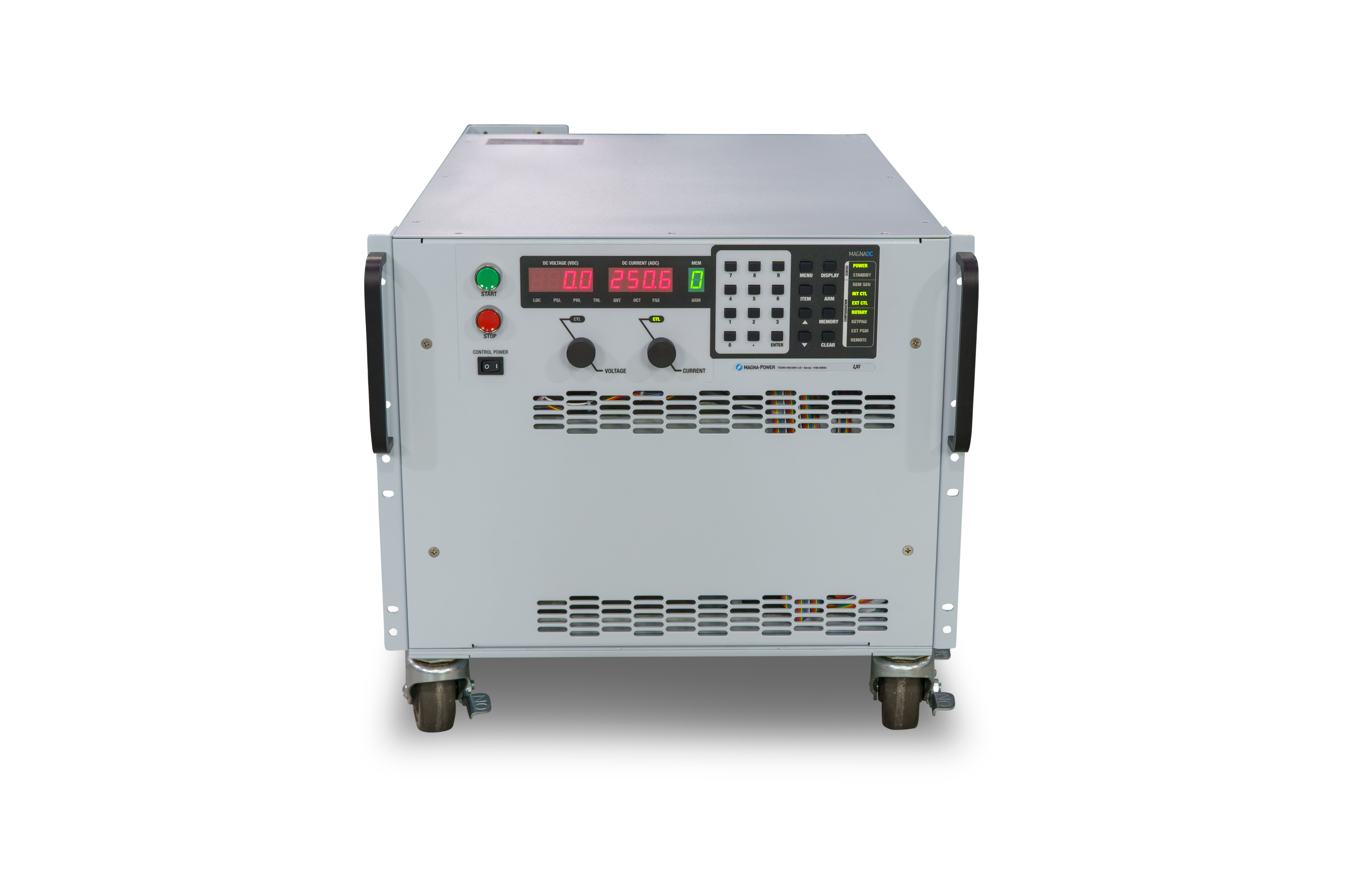
The MS Series was built using the same 15 kW power processing modules as the original TS Series, only packaged in a floor-standing cabinet and expanding into higher power levels. The available The MS Series models covered a very wide output range, spanning from voltage levels from 5 Vdc up to 6000 Vdc (floating) and current levels up to 4500 Adc. 30 kW model were available in a 12U 31.5" (80.0 cm) high enclosure, while 45 kW to 75 kW models were available in a 24U 51" (129.5 cm) high enclosure; all enclosures came with casters. In addition, there were several special low voltage high current models, enabling a more cost-effective solution for these requirements. All MS Series power supplies came standard with isolated 37-pin external I/O, RS232, Remote Interface Software, IVI drivers for integration into a variety of programming environments.
A higher power 25 kW module was created for the TS Series, along with a new steel sub-frame mechanical design for higher power models. The updated mechanical design provided a major reduction is size for higher power units, and the TS Series was expanded to include 50 kW, 75 kW and 100 kW modules in a fraction of the size of the MS Series. The MS Series products were discontinued, but with the same controller, firmware and interfaces, the TS Series offers an easy migration path.
Recommended Replacement Product
TS Series Programmable DC Power Supply
Resources for the MS Series
Documentation
Drawings
Drivers
Software


