MT Series
Programmable DC Power Supply
- Size
- 60U to 90U+
- Power
- 150 kW to 3 MW+
- Manufactured
- USA
- Build-time
- 4-6 weeks
The MT Series delivers 150 to 250 kW of programmable DC power per floor-standing cabinet, using high-frequency IGBT current-fed power processing and integrated AC input breakers for robust, high-power conversion. Systems scale into the multi-megawatt range via UID47 master-slave control, while embedded 12-pulse harmonic neutralizers on 250 kW models—and optional 24- or 48-pulse external neutralizers—minimize THD to meet demanding power-quality requirements in large test bays, drives, and renewable-energy emulation.
Key Features
- 150 kW and 250 kW modules
- High-frequency IGBT current-fed topology
- Multi-megawatt scaling via UID47 control
- Integrated AC input breaker standard
- Harmonic neutralizers for low grid THD

Talk with an expert


High-power performance, harmonic control, and configurability.
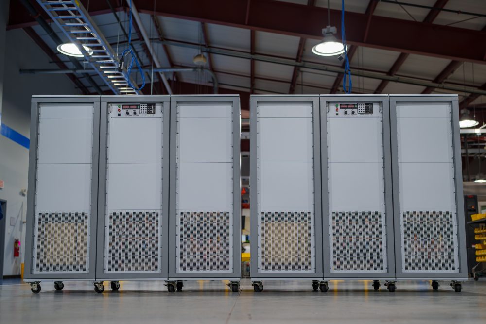
High-performance DC power at scale
Precise, stable output for multi-kilowatt to multi-megawatt systems.
With a wide range of high current and high voltage up to 6,000 Vdc (floating), the MT Series systems deliver fast transient response, high-accuracy programming and measurement, and low output ripple across a wide range of power levels. With constant-voltage or constant-current operation and automatic crossover, they respond quickly to changing loads and hold tightly to their targets—well suited for high-power test stands, industrial process power, and multi-megawatt installations where performance matters.
Configured-to-order with integrated options
Rich standard features, extended when needed.
Like the rest of the MagnaDC line, MT Series supplies start with a strong control base: SCPI over RS232, isolated rear User I/O, LabVIEW and IVI drivers, and Remote Interface Software included. From there, integrated options let you tailor each system for its role—High Isolation Output (+ISO) for extended series stacking, High Slew Rate Output (+HS) for faster dynamics, LXI TCP/IP Ethernet (+LXI) and IEEE-488 GPIB (+GPIB) for additional communications, plus protection and mechanical options such as an Integrated Blocking Diode (+BD) and Pedestal Base (+PB) for fixed installations.

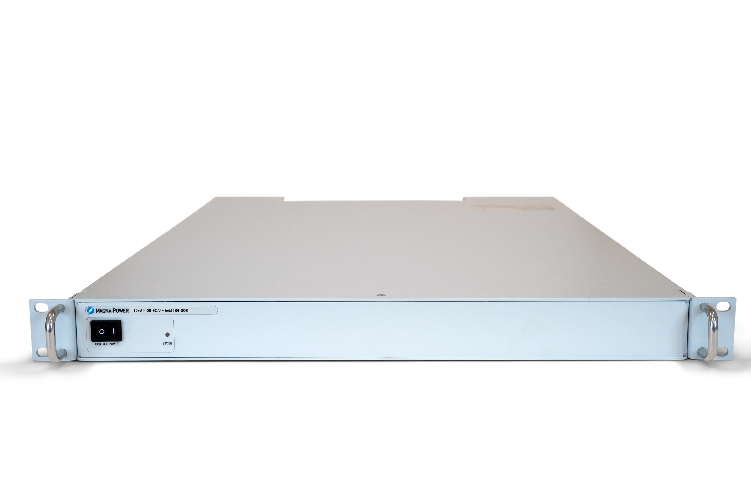
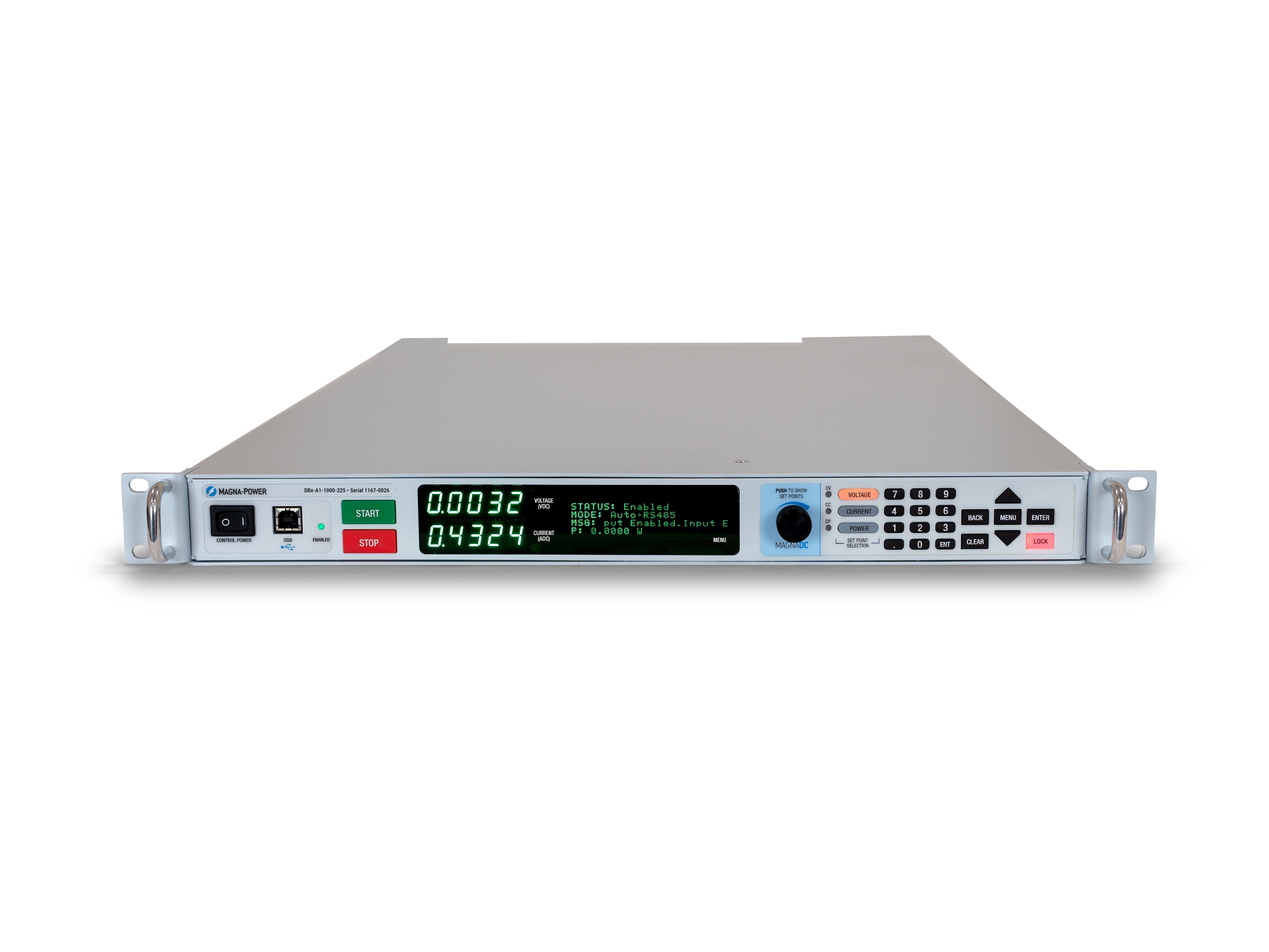
Stepless front-panel control with blank panel option
Hands-on where you want it, hidden where you don’t.
The standard D Version front panel provides rotary and key-based control, bright digital metering, and clear status indicators, so operators can configure setpoints, start and stop the supply, and see system health at a glance. For OEMs and production tools, the optional blank (C-version) front panel removes local controls altogether while retaining full control via communication interfaces and rear 37-pin user I/O, keeping systems secure, clean, and operator-proof.
Harmonic Neutralizers for cleaner high-power systems
Reduce THD at the source for easier power-quality compliance.
Input current harmonics are an inherent by-product of three-phase rectifiers: a standard 6-pulse front end produces harmonic currents at 1, 5, 7, 11, 13… times the fundamental, with the 5th and 7th components alone at roughly 20% and 14% of the fundamental. These currents can excite sensitive loads—such as lighting ballasts with series capacitors/inductors—and make meeting power-quality guidelines like IEEE 519 more challenging. The most reliable way to minimize harmonic issues is to eliminate harmonic current at the source.
For high-power systems, Magna-Power manufactures specially wound Harmonic Neutralizers that multiply the number of input phases and dramatically cut input current THD, passively. Standard 1.5–150 kW Magna-Power supplies draw a 6-pulse waveform, while 250 kW MT Series and 500 kW ML Series models embed a 12-pulse Harmonic Neutralizer and 1000 kW ML Series models embed a 24-pulse Harmonic Neutralizer—transparent to the user.

Rugged by design: safety + reliability, as you'd expect from Magna-Power.

Reliable current-fed power processing
Rugged by design: self-protecting topology for uptime.
MagnaDC power supplies utilize a high-frequency, current-fed architecture that adds a control stage beyond conventional voltage-fed designs. This topology inherently limits fault energy—avoiding fast-rising current spikes and magnetic core saturation so the supply self-protects and your load stays safe. Paired with state-of-the-art SiC power semiconductors, Magna DC power supplies delivers class-leading power density, efficiency, and reliability, including continuous full-power operation up to 50°C ambient.
- Current-fed architecture with an added control stage vs. voltage-fed.
- Inherent surge immunity—no current spikes or core saturation.
- Self-protecting behavior under fault conditions.
- SiC devices for high density and efficiency; full power to 50°C.
Safety features & interlock
Soft-start, programmable protection, and a mechanical line disconnect for true safety.
MagnaDC supplies start gently and watch continuously. A soft-start stage keeps inrush below steady-state draw, while built-in diagnostics monitor line, thermal, and control conditions. In standby or on a diagnostic fault, an embedded AC contactor mechanically disconnects the mains, assuring the unit only processes power when intended. Faults are shown on the front-panel status display, through 5V digital outputs, and are queryable via SCPI.
- Programmable trips: Over voltage (OVT) and over current (OCT).
- Control integrity: Program-line over-voltage detection.
- Over temperature product with multiple distributed thermal switches.
- Interlock/E-stop fault monitoring as a standard diagnostic.
- Field integration: 5V interlock input (with 5V reference) for a dry-contact, latching inhibit with control power maintained.
From lab scripts to factory PLCs, flexible programming & integration.
Software integration made easy
Readable commands, quick results—works with any language.
MagnaDC power supplies exposes a clear, text-based API with native SCPI, an ASCII-based command language sent over socket communications. Over 40 well-documented commands cover start/stop, set points for voltage, current, high-accuracy measurements, and full configuration—so your scripts and systems go from proof-of-concept to production fast.
- SCPI command sets with consistent behavior.
- Start/stop & protections: enable output, set trip limits, query status.
- High-accuracy reads: voltage, current, power, and sense feedback.
- Developer-driven documentation & examples.
import serial
magnaPower = serial.Serial(port='COM4', baudrate=19200)
magnaPower.write('*IDN?\n'.encode())
print magna_power.readline()
magnaPower.write('VOLT 0\n'.encode())
magnaPower.write('CURR 0\n'.encode())
magnaPower.write('OUTP:START\n'.encode())
magnaPower.write('VOLT 270\n'.encode())
currSetPoints = [50, 100, 150, 250]
for currSetPoint in currSetPoints:
    print 'Setting Current to %s A' % currSetPoint
    magnaPower.write('CURR {0}\n'.format(currSetPoint).encode())
    magnaPower.write('MEAS:VOLT?\n'.encode())
    print magnaPower.readline()
    time.sleep(20)
magnaPower.write('OUTP:STOP\n'.encode())
magnaPower.close()
magna_power = serial('COM4', 'BaudRate', 19200);
fopen(magnaPower);
fprintf(magnaPower,'*IDN?');
idn = fscanf(magnaPower);
fprintf(magnaPower,'VOLT 0');
fprintf(magnaPower,'CURR 0');
fprintf(magnaPower,'OUTP:START');
fprintf(magnaPower,'VOLT 270');
for currSetPoint in [50, 100, 150, 250]
    display('Setting Current to '+currSetPoint+' A');
    fprintf(magnaPower, 'CURR '+currSetPoint);
    fprintf(magnaPower,'MEAS:VOLT?');
    display(fscanf(magnaPower));
    pause(20);
end
#include <stdio.h>
#include <stdint.h>
#include <string.h>
#include <windows.h>

int main()
{
    printf("Opening connection.\n");

    uint8_t recvBuffer[sizeof(uint8_t) * 256];
    memset(recvBuffer, 0, 256);

    // Choose the serial port name.
    // COM ports higher than COM9 need the \\.\ prefix, which is written as
    // "\\\\.\\" in C because we need to escape the backslashes.
    const char* device = "\\\\.\\COM4";

    // Choose the baud rate (bits per second).
    uint32_t baud_rate = 19200;

    HANDLE port = open_serial_port(device, baud_rate);
    if (port == INVALID_HANDLE_VALUE) { return 1; }

    char* scpiCmd = (char*)"*IDN?\n";
    size_t cmdLen = strlen(scpiCmd);
    int result = write_port(port, (uint8_t*)scpiCmd, cmdLen);
    if (result < 0)
        return -1;

    result = read_port(port, recvBuffer, 256);
    printf("Sent: %s\nReceived: %s\n", scpiCmd, recvBuffer);

    scpiCmd = (char*)"VOLT 0\n";
    cmdLen = strlen(scpiCmd);
    result = write_port(port, (uint8_t*)scpiCmd, cmdLen);
    if (result < 0)
        return -1;

    scpiCmd = (char*)"CURR 0\n";
    cmdLen = strlen(scpiCmd);
    result = write_port(port, (uint8_t*)scpiCmd, cmdLen);
    if (result < 0)
        return -1;

    scpiCmd = (char*)"OUTP:START\n";
    cmdLen = strlen(scpiCmd);
    result = write_port(port, (uint8_t*)scpiCmd, cmdLen);
    if (result < 0)
        return -1;

    scpiCmd = (char*)"VOLT 270\n";
    cmdLen = strlen(scpiCmd);
    result = write_port(port, (uint8_t*)scpiCmd, cmdLen);
    if (result < 0)
        return -1;

    char setPoints[4][5] = {"50", "100", "150", "200"};
    char setPointBuffer[40];
    scpiCmd = (char*)"MEAS:VOLT?\n";

    for (int i = 0; i < 4; i++)
    {
        sprintf(setPointBuffer, "CURR %s\n", setPoints[i]);
        printf("Setting current to %s A\n", setPoints[i]);
        cmdLen = strlen(setPointBuffer);
        result = write_port(port, (uint8_t*)setPointBuffer, cmdLen);
        if (result < 0)
            return -1;
        memset(recvBuffer, 0, 256);
        result = read_port(port, recvBuffer, 256);
        printf("Received: %s\n", recvBuffer);
        Sleep(20000);  // 20000ms = 20s
    }

    scpiCmd = (char*)"OUTP:STOP\n";
    cmdLen = strlen(scpiCmd);
    result = write_port(port, (uint8_t*)scpiCmd, cmdLen);
    if (result < 0)
        return -1;

    CloseHandle(port);

    printf("Connection closed.\n");
    return 0;
}
using System;
using System.IO.Ports;
using System.Threading;

namespace SerialCommunicationInCSharp
{
  public class Program
  {
    static bool _continue;
    static SerialPort serialPort;

    public static void Main(string[] args)
    {
      Thread readThread = new Thread(Read);

      Console.WriteLine("Opening connection.");

      // Create a new SerialPort object with default settings.
      serialPort = new SerialPort("COM4", 19200, Parity.None, 8, StopBits.One);

      // Set the read/write timeouts
      serialPort.ReadTimeout = 500;
      serialPort.WriteTimeout = 500;

      serialPort.Open();
      _continue = true;
      readThread.Start();

      Console.WriteLine("Sending: *IDN?");
      serialPort.WriteLine("*IDN?");

      serialPort.WriteLine("VOLT 0");
      serialPort.WriteLine("CURR 0");
      serialPort.WriteLine("OUTP:START");
      serialPort.WriteLine("VOLT 270");

      string[] currSetPoints = { "50", "100", "150", "250" };
ß
      for(int i = 0; i < currSetPoints.Length; i++)
      {
        serialPort.WriteLine(String.Format("'CURR {0}", currSetPoints[i]));
        serialPort.WriteLine("MEAS:VOLT?");
        Thread.Sleep(20000);
      }

      serialPort.WriteLine("OUTP:STOP");

      Console.WriteLine("Closing connection.");
      _continue = false;
      serialPort.Close();
      }

    public static void Read()
    {
      while (_continue)
      {
        try
        {
          string message = serialPort.ReadLine();
          Console.WriteLine("Received: " + message);
        }
        catch (TimeoutException) { }
      }
    }
  }
}

External User I/O for PLC control or PHIL simulation
Wire it like an I/O module—no extra isolation needed.
Via the included rear 37-pin User I/O connector, MagnaDC supplies can be fully driven and monitored by external signals or a PLC. Voltage, current, OVT, and OCT set points are programmed with 0–10 V analog inputs, while each diagnostic condition has its own +5V digital status pin. Built-in +2.5V, +5V, and +10V reference rails let you use dry contacts without adding external supplies. All I/O is isolated from the output and referenced to earth ground as standard.
- 0–10 V analog programming for V, I, OVT, and OCT.
- Per-fault digital outputs: each diagnostic has its own +5V pin.
- Isolated user I/O referenced to earth ground—no extra isolators.
- With High Slew Rate Output (+HS), high-bandwidth response and fast rise times support HIL/PHIL simulation applications.
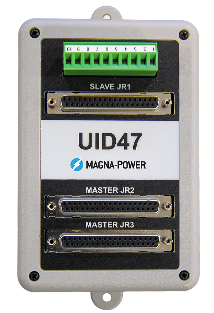
High-performance master-slave operation
Scale voltage or current without sacrificing performance.
All MagnaDC supplies support master-slave operation, using gate-drive signals from the master when configured for parallel, so the whole stack behaves like a single supply—with one control loop and no noisy long analog references. The optional UID47 accessory simplifies wiring for series or parallel sets with near-equal sharing.
- Single control loop parallel operation: Master gate-drive to slaves for consistent dynamics.
- Plug & play with the UID47, enabling parallel or series stacks with current/voltage sharing.
- Series up to the DC isolation rating without added hardware.
No additional ORing diodes required for parallel operation.
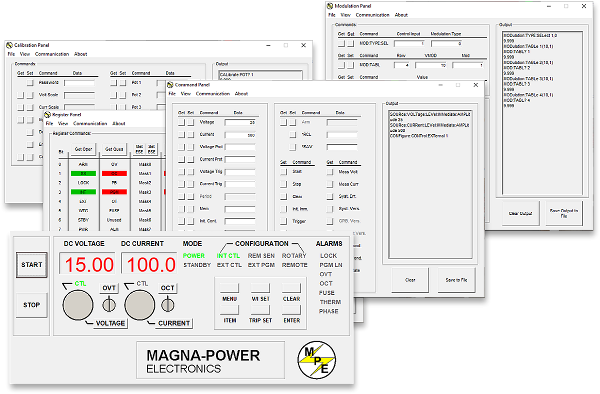
Magna-Power software, LabVIEW & IVI drivers
From virtual front panel to full automation—out of the box.
Every MagnaDC supply includes an IVI driver and NI LabVIEW driver with a full set of VIs, plus example programs so you can get talking to the hardware in minutes. For direct front-panel-style control from a PC, Magna-Power’s Remote Interface Software provides a rich view into the supply—from commands and registers to calibration and firmware.
-
IVI & NI LabVIEW drivers included with full VI set.
-
Example programs to jump-start integration and testing.
-
Remote Interface Software with:
-
Virtual front panel for manual control
-
Command panel to explore and send commands
-
Register panel for live status monitoring
-
Calibration panel for internal digital potentiometers
-
Firmware panel for in-place upgrades
-
Modulation panel to emulate non-linear profiles
-
-
All communication interfaces supported across software and drivers for a consistent programming experience.
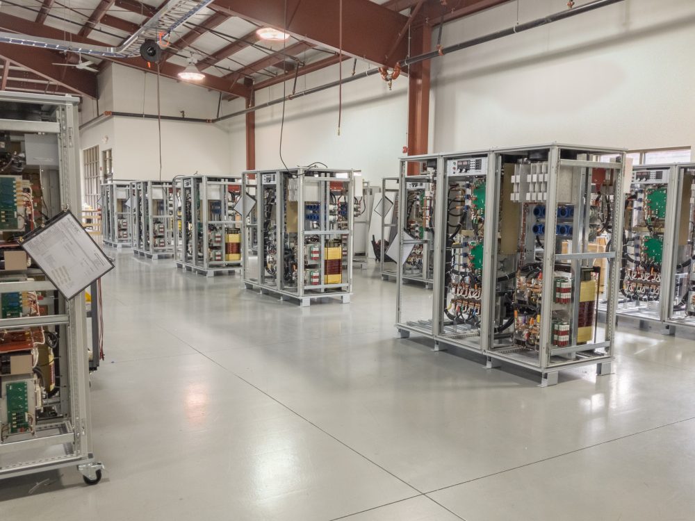
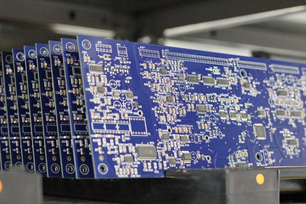
State-of-the-art USA manufacturing with worldwide support

Made in the USA
Vertically integrated manufacturing for full quality control.
Magna-Power products are designed, built, tested, and serviced at Magna-Power’s 73,500 sq-ft headquarters in Flemington, New Jersey, where metalwork, magnetics, PCB assembly, and burn-in are all done in-house for tight control over quality, cost, and lead-time.
- USA-built: Engineering, manufacturing, and service under one roof.
- In-house production: Metalwork, magnetics, SMT PCBs, and finishes.
- Proven reliability: Every unit fully tested, calibrated, and burned in.
Worldwide service & OEM parts support
Factory expertise, local response.
Magna-Power backs its products with factory and authorized service centers across North America, Europe, the UK, Asia-Pacific, East Asia, and South America—using factory procedures and genuine parts to restore units to original specifications, in or out of warranty.
- Global coverage: HQ in New Jersey plus regional authorized service centers.
- Consistent repairs: Factory diagnostics, work instructions, and system diagrams.
- Genuine OEM parts: Tested replacement assemblies for predictable, low-downtime service.
Model Ordering Guide
For both ordering and production, MT Series models are uniquely defined by several key characteristics, as defined by the following diagram:

MT Series Models
There are 49 different models in the MT Series spanning power levels: 150 kW and 250 kW. To determine the appropriate model:
- Select the desired Max Voltage (Vdc) from the left-most column.
- Select the desired Max Current (Adc) from the same row that contains your desired Max Voltage.
- Construct your model number according to the model ordering guide.
| Max Voltage Vdc |
150 kW | 250 kW | 500 kW1 | 750 kW1 | 1000 kW1 | Ripple mVrms |
Efficiency |
|---|---|---|---|---|---|---|---|
| Max Current Adc | |||||||
| 32 | 4500 | — | — | — | — | 40 | 90% |
| 40 | 3750 | 6000 | 12000 | 18000 | 24000 | 40 | 91% |
| 50 | 3000 | 5000 | 10000 | 15000 | 20000 | 50 | 91% |
| 60 | 2500 | 4160 | 8320 | 12480 | 16640 | 60 | 91% |
| 80 | 1850 | 3000 | 6000 | 9000 | 12000 | 60 | 91% |
| 100 | 1500 | 2500 | 5000 | 7500 | 10000 | 60 | 91% |
| 125 | 1200 | 2000 | 4000 | 6000 | 8000 | 100 | 91% |
| 160 | 900 | 1500 | 3000 | 4500 | 6000 | 120 | 91% |
| 200 | 750 | 1250 | 2500 | 3750 | 5000 | 125 | 91% |
| 250 | 600 | 1000 | 2000 | 3000 | 4000 | 130 | 92% |
| 300 | 500 | 833 | 1666 | 2499 | 3332 | 160 | 92% |
| 375 | 400 | 660 | 1320 | 1980 | 2640 | 170 | 92% |
| 400 | 375 | 625 | 1250 | 1875 | 2500 | 180 | 92% |
| 500 | 300 | 500 | 1000 | 1500 | 2000 | 220 | 92% |
| 600 | 240 | 400 | 800 | 1200 | 1600 | 250 | 92% |
| 800 | 180 | 300 | 600 | 900 | 1200 | 300 | 92% |
| 1000 | 150 | 250 | 500 | 750 | 1000 | 400 | 92% |
| 1250 | 120 | 200 | 400 | 600 | 800 | 500 | 92% |
| 1600 | 90 | 150 | 300 | 450 | 600 | 600 | 92% |
| 2000 | 75 | 125 | 250 | 375 | 500 | 800 | 92% |
| 2500 | 60 | 100 | 200 | 300 | 400 | 900 | 92% |
| 3000 | 50 | 80 | 160 | 240 | 320 | 1000 | 92% |
| 4000 | 36 | 60 | 120 | 180 | 240 | 1100 | 92% |
| 5000 | 30 | 50 | 100 | 150 | 200 | 92% | |
| 6000 | 25 | 41.6 | 83.2 | 124.8 | 166.4 | 92% | |
| AC Input Voltage Vac |
Input Current Per Phase Aac | ||||||
| 380/415 Vac, 3Φ | 276 | 440 | 880 | 1320 | 1760 | ||
| 440/480 Vac, 3Φ | 238 | 380 | 760 | 1140 | 1520 | ||
1Power levels are achieved through master-slave parallel of 250 kW models. Contact sales for systems up to 3,000 kW.
Specifications are subject to change without notice. Unless otherwise noted, all specifications measured at the product's maximum ratings.
AC Input Specifications
415 Vac (operating range 373 to 456 Vac)
440 Vac (operating range 396 to 484 Vac)
480 Vac (operating range 432 to 528 Vac)
> 0.96 at maximum power, 250 kW models
DC Output Specifications
Current mode: ± 0.02% of full scale
Current mode: ± 0.04% of full scale
Model specific. Refer to chart of available models.
< 200 ms for a programmed output current change from 0 to 63%
< 10 ms for a programmed output current change from 0 to 63%
2 Hz with remote analog current programming
45 Hz with remote analog current programming
Programming Interface Specifications
LXI TCP/IP Ethernet RJ45 (Option +LXI)
IEEE-488 GPIB (Option +GPIB)
Referenced to Earth ground; isolated from power supply output
See User Manual for pin layout
Accuracy Specifications
External User I/O Specifications
Current output monitoring: 100 Ω
+10V reference: 1 Ω
Output: 0 to 5 Vdc, 5 mA drive capacity
Physical Specifications
67" H x 48" W x 31.5" D (170.2 x 121.9 x 80.0 cm)
1600 lbs (725.8 kg)
67" H x 48" W x 31.5" D (170.2 x 121.9 x 80.0 cm)
2100 lbs (952.5 kg)
67" H x 72" W x 31.5" D (170.2 x 182.9 x 80.0 cm)
3300 lbs (1496.9 kg)
Environmental Specifications
0.06%/°C of maximum output current
Regulatory Specifications
CISPR 22 / EN 55022 Class A
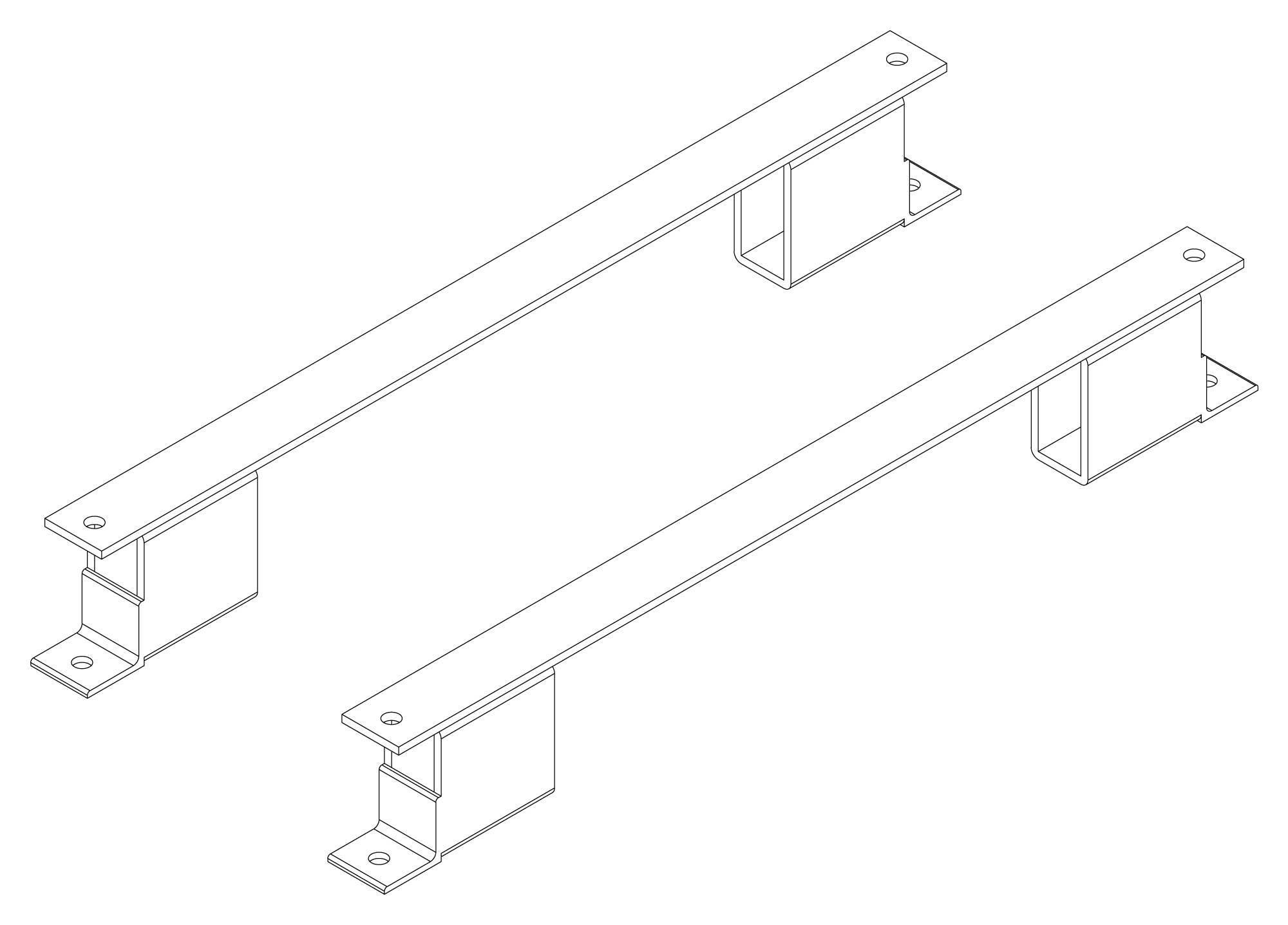
The following are vectorized diagrams for the MT Series. Refer to the Downloads section for downloadable drawings.


Integrated Options
Standard integrated options are available for Magna-Power products, allowing the product's performance and communication interfaces to be tailors to the specific application.
- Option
- +ISO
- Option
- +HS
- Option
- +GPIB
- Option
- +BD

Accessories
External accessories and integration services available for this product.