8. Operation: Computer Programming
Every MagnaLOAD DC electronic load has the following communication connections available:
| Interface | Location | Connector | Standard/Optional | Priority |
|---|---|---|---|---|
| USB (Host) | Front | JR1 | Standard | 1 |
| USB (Host) | Rear | JR2 | Standard | 2 |
| RS485 | Rear | JR3 | Standard | 5 |
| LXI TCP/IP Ethernet | Rear | JR6 | Optional | 3 |
| IEEE-488 GPIB | Rear | JR6 | Optional | 3 |
All of the communication connections share the same internal communications bus; only one communication interface can be used at a time. The front panel menu display will always show what communication interface is active. The MagnaLOAD electronic load
The front panel USB takes the highest computer interface priority. When a front or rear USB connection is physically made the MagnaLOAD electronic load will automatically switch to computer control from RS485 to the newly connected USB port. Conversely, when a command is sent via the optional LXI TCP/IP Ethernet or IEEE-488 GPIB interface, the MagnaLOAD electronic load will automatically switch to computer control from the Ethernet or GPIB port with the new communication. Switching back to USB requires disconnecting and reconnecting the USB plug or power cycling the MagnaLOAD electronic load. RS485 is the lowest priority interface and only has control when the USB ports are disconnected and the there is no communication over LXI TCP/IP Ethernet or IEEE-488 GPIB interfaces.
8.1. Communications Validation
It is import to establish and validate basic communications functions before starting a sophisticated computer interface project. The following instructions are intended to help customers isolate problems with computer settings, wiring, and electrical noise. The validation instructions also provide a common environment for which Magna-Power can reproduce issues in support cases and better serve the customer.
If not already installed, Magna-Power Electronics recommends using the terminal emulation programs called PuTTY for creating serial connections.
8.1.1. USB Communications Validation
USB uses serial communications. To test, make a physical connection between the USB Type B connector on the MagnaLOAD electronic load and the USB Type A on the computer. Pin outs for these connectors are described in USB Interface. Connect using the standard USB cable included with the product. The front panel shows the active state of the communications interface. If the front USB was connected, the display should transition from RS485 to USB2. If the rear USB was connected, the display should transition from RS485 to USB1. After a physically connection is made a session connection is made with the MagnaLOAD electronic load.
Open Device Manager and under ports make note of the COM port number, as shown in Fig. 8.1.
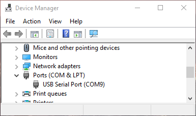
Fig. 8.1 Window Device Manager
Open PuTTY and select the Session menu. Enter the COM port that was found in Device Manger and enter 115200 for the Speed. Set the Connection type to Serial, as shown in Fig. 8.2.
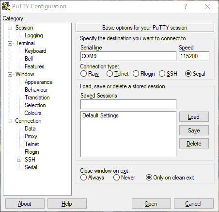
Fig. 8.2 PuTTY Session Settings
Select the Terminal menu and set Force on for all options. Press the Open button to start the communications session with the MagnaLOAD electronic load, as shown in Fig. 8.3.
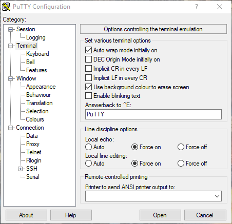
Fig. 8.3 PuTTY Terminal Settings
Session should open a new blank window. Type the command:
*IDN?
If settings match and wiring connections are correct, the session window should look like Fig. 8.4.
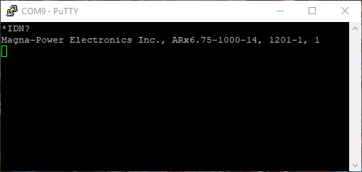
Fig. 8.4 PuTTY Terminal Session Output
8.1.2. RS485 Communications Validation
RS485 also uses serial communications. Most customers will need a USB-to-RS485 adapter (not included) to allow the computer to connect to RS485. Any RS485 adapter should work provided it supports half-duplex communication and 115200 baud. Magna-Power Electronics recommends USB-COM485-PLUS1 and USB-COM485-PLUS4 adapters from FTDI. The adapter will serial port(s) in Windows Device Manager.
Customers will also need to create their own cable. The MagnaLOAD electronic load interfaces to RS485 through a RJ45 connector located in the rear. RJ45 mates readily with Category 5 Ethernet cables. When crimping wires to the connector make sure to follow the pins outs described in RS485 Interface.
By default, the RS485 interface is active when no other communication interface cables are connected. The front display will always show the RS485 state even when the wire is disconnect. Once the computer and MagnaLOAD electronic load are physically connected, open PuTTY, and follow the instructions described in USB Communications Validation to make a serial connection and test it.
8.2. Programming Methods
There is a large selection of commands and interfaces that can be used to program the MagnaLOAD electronic load. A computer can communicate with MagnaLOAD electronic load using either USB, RS485, Ethernet, or GPIB. A programmable logic controller can control MagnaLOAD electronic load operation through analog IO and digital IO pins exposed on the rear connector.
The MagnaLOAD electronic load implements Standard Commands for Programmable Instrumentation (SCPI), a protocol that communicates using simple ASCII commands through a standard serial port. These commands are detailed in SCPI Command Set. Simple digital and analog interfaces to the product are detailed in Operation: External User I/O.
8.3. USB Communications
Two USB ports come standard on all MagnaLOAD electronic loads. Magna-Power Electronics implements the USB protocol stack using FTDI chip set, a plug and play (PnP) device, that automatically install drivers. Connection to a computer can be established using a standard USB cable, with one end connected to the MagnaLOAD electronic load and the other to a controlling device. The communication port parameters are shown in Table 8.1. Guidelines on establishing simple serial session is discussed in USB Communications Validation.
| Parameter | Value |
|---|---|
| Baud | 115200 |
| Data bits | 8 |
| Stop bits | 1 |
| Parity | None |
| Flow Control | XON/XOFF |
8.4. RS485 Communications
One RS485 port comes standard on all MagnaLOAD electronic loads. Connection to a computer can be established using a modified Ethernet cable (not included), with one end connected to the MagnaLOAD electronic load and the other to a controlling device. The communication port parameters are shown in Table 8.1.
8.5. LXI TCP/IP Ethernet Communications
MagnaLOAD DC electronic load products are available with an optional LXI TCP/IP Ethernet interface (+LXI). The LXI TCP/IP Ethernet interface meets the LXI Class C, Revision 1.4 standard. When specified at time of order, an Ethernet interface module is installed, providing an embedded Ethernet port for communications.
Ethernet connections can be made though the MagnaWEB, terminal emulation programs like PuTTY, user written software, or through a computer’s web page browser. In the latter case, a web server programmed into the LXI TCP/IP Ethernet interface module, allows the power supply to communicate to a computer using a web browser.
8.5.1. Address Negotiation
By default, DHCP is enabled on the MagnaLOAD electronic load. If the Ethernet board does not discover a DHCP server, the MagnaLOAD electronic load will default to the Auto-IP configuration as defined in Table 8.2. The device then automatically selects an IP address from 169.254.###.### and subnet as described in RFC 3927 (Request for Comments 3927 - Dynamic Configuration of IPv4 Link-Local Addresses). This routine is used by most computer operating systems.
| IP Address | 169.254.###.### |
|---|---|
| Subnet Mask | 255.255.0.0 |
| Default Gateway | 0.0.0.0 |
| DNS Server | 0.0.0.0 |
| MAC Address | 01:1E:6F:##:##:## |
8.5.2. Connectivity
The LAN status LED, located at the rear of the MagnaLOAD electronic load, provides LAN fault and device identification, defined as follows:
- On - Normal Operation
- The device has a properly configured IP address and the network cable is connected.
- Flashing - Device Identify
- The LXI Device Identification function was enabled via the Instrument Identification web page. This identification can help the user to quickly locate the unit and distinguish it from similar devices.
- Off - LAN Fault
- The device is experiencing one or more of the following LAN fault conditions: failure to acquire a valid IP address, detection of a duplicate IP address on the network, failure to renew an already acquired DHCP lease, or the LAN cable is disconnected.
8.6. IEEE-488 GPIB Communications
MagnaLOAD DC electronic load products are available with an optional IEEE-488 GPIB interface. When specified at time of order, an IEEE-488 GPIB interface module is installed internally, providing an embedded IEEE-488 GPIB port available for communiations. With two UART ports available, RS232 and IEEE-488 GPIB, the one first receiving communications after power on is the port that is activated. Once activated, the other UART port cannot be recognized unless there has been a period of inactivity for 5 minutes. After this period, a new UART port can be recognized by sending communications. The IEEE-488 GPIB terminal, connector JS4, is detailed in
All of the SCPI subsystem commands in the previous section can be initiated using RS232, optional IEEE-488 GPIB (+GPIB), or optional LXI TCP/IP Ethernet (+LXI) communications.
The IEEE-488 standard defines a method for status reporting. As illustrated in [NEED FIGURE], the reporting method uses the IEEE-488 Status Byte (STB). Three bits of this byte are defined as:
- Master Status Summary (MSS) Bit
- Event Status Bit (ESB)
- Message Available (MAV) Bit
The Master Status Summary (MSS) is an unlatched bit. When the Status Byte Register is read using a Status Byte Register query, bit 6 will be 1 if there are any conditions requiring service.
The STB is masked by the Service Request Enable Register (SRE) to allow the user to mask specific or all events from setting the MSS bit to 1. The MSS bit is obtained by logical OR’ing the bits of the enabled Status Byte Register.
The Event Status Bit (ESB) is set when one of the events defined in the Event Status Register (ESR) [REFERENCE ESR TABLE HERE] has occurred. Like the STB, the ESR is masked by the Event Status Enable Register (ESE) to allow the user to mask specific or all events from setting the ESB to 1.
The Message AVailable (MAV) bit is set to 1 when a message is available in the output buffer.
8.6.1. IEEE-488 GPIB Communications with NI MAX
National Instruments offers Measurement and Automation Explorer (MAX), a Graphical User Interface, as a terminal emulation program for configuring an Interchangeable Virtual Instrument (IVI). MAX is usually installed with one of National Instrument’s Application Development Environments such as LabVIEW, Measurement Studio, or with hardware product drivers such as NI-488 and NI-DAQ.
To operate the power supply with MAX, the instrument must first be located for communications. The following steps describe this procedure.
- Run the MAX application program.
- In the Configuration window, press the + sign to the left of Devices and Interfaces to view the installed devices.
- If there is more than one IEEE-488 GPIB device listed, then select the correct GPIB device.
- Press Scan for Instruments on the menu bar and wait several seconds.
- At least one instrument should appear under the GPIB controller. If no instruments appear, then refer to [REFERENCE PROGRAMMING GPIB SECTION] to verify the correct setup.
- On the menu bar, press Communicate with Instrument. The NI-488 Communicator dialog box should appear.
- In the NI-488 Communicator dialog box, press the Configure EOS button. The Termination Method dialog box should appear.
- Select the option Send EOI at end of Write. Enter 0 into the EOS byte. Press OK.
| Pin | Definition | Pin | Definition |
|---|---|---|---|
| 1 | DIO1/Data line | 13 | DIO5/Data line |
| 2 | DIO2/Data line | 14 | DIO6/Data line |
| 3 | DIO3/Data line | 15 | DIO7/Data line |
| 4 | DIO4/Data line | 16 | DIO8/Data line |
| 5 | EOI/End or Identify | 17 | REN/Remote Enable |
| 6 | DAV/Data Valid | 18 | DAV/Gnd |
| 7 | NRFD/Not Ready for Data | 19 | NRFD/Gnd |
| 8 | NDAC/Not Data Accepted | 20 | NDAC/Gnd |
| 9 | IFC/Interface Clear | 21 | IFC/Gnd |
| 10 | SRQ/Service Request | 22 | SRQ/Gnd |
| 11 | ATN/Attention | 23 | ATN/Gnd |
| 12 | Shield | 24 | Gnd |