The following table provides the suggested DC ampacities of AWG (American Wire Guage) copper wire. Paralleled DC cables may be required for larger-ampacity DBx Module Add-On. Ampacity ratings ar based on single conductor in 25 °C ambient free air, with a conductor rated for 60 °C.
Tip
For DC cabling, Magna-Power highly recommends flexible General Cable Carol® Brand Carolprene® cable, used by Magna-Power and many of its customers.
Caution
Make sure DC connections are tightened in accorandance with Magna-Power’s provided torque specification to avoid overheating of the bus bars.
Wire Size (USA) |
Equivalent Wire Size
(International)
|
Wires Per Output Terminal |
Maximum Current |
|---|---|---|---|
6 AWG |
10 mm2 |
1 |
85 Adc |
4 AWG |
25 mm2 |
1 |
110 Adc |
3 AWG |
25 mm2 |
1 |
130 Adc |
2 AWG |
35 mm2 |
1 |
150 Adc |
1 AWG |
50 mm2 |
1 |
170 Adc |
1/0 AWG |
50 mm2 |
1 |
200 Adc |
2/0 AWG |
70 mm2 |
1 |
235 Adc |
3/0 AWG |
95 mm2 |
1 |
275 Adc |
4/0 AWG |
120 mm2 |
1 |
315 Adc |
1/0 AWG |
50 mm2 |
2 |
400 Adc |
2/0 AWG |
70 mm2 |
2 |
470 Adc |
3/0 AWG |
95 mm2 |
2 |
550 Adc |
4/0 AWG |
120 mm2 |
2 |
630 Adc |
1/0 AWG |
50 mm2 |
4 |
800 Adc |
2/0 AWG |
70 mm2 |
4 |
940 Adc |
3/0 AWG |
95 mm2 |
4 |
1100 Adc |
4/0 AWG |
120 mm2 |
4 |
1260 Adc |
Notes:
Capacity for AWG wires derived from the National Electric Code. Maximum ambient temperature: 40°C. Maximum wire temperature: 90°C. Continuous duty with wires in free air, not bundled or in conduit.
Capacity of aluminum wire is approximately 84% of the capacity listed for copper wire.
For higher current levels, it’s recommended to use bus bars with additional fastening locations allowing for more wire feeds feeds or direct bus bar connection to the load.
A chassis ground reference is also provided on the rear near the DC bus bars, which is tied to the AC input ground. The recommended torque for the ground stud is 55 in-lbf (6.21 N-m).
For rack-mount models, after connections are made, screw the four standoffs into the back panel and place the protective shield over the connections.
For DC bus connections exceeding 315 Adc, Magna-Power recommends multiple runs of 4/0 cabling in parallel. Custom DC bus work may be required to either extend the DBx Module Add-On’s DC bus bars allowing additional DC wire connections, or to make a direct connection with the DC bus work. With increased cable bundling, the ampacity rating of the DC cables will decrease, as less surface area is in free air to cool the wires.
Remote Sense Connection
Remote sensing can improve regulation at a remote reference point. For example, appreciable voltage drop can occur in the wire between the power supply and load as the current increases. By default, the load operates in local sense, where feedback is internally connected to the load’s input terminals. However, the load can also operate in remote sense, and compensate for wire voltage drop by connecting its high-impedance sense wires to the power source terminals. When the remote sense setting is enabled the feedback measurements are taken from the remote sense leads.
The remote sense setting is accessible from either the front panel configuration or by computer command. Magna-Power recommends using 20 AWG wires with the remote sense screw terminals. Connect the DBx Module Add-On’s positive remote sense lead to the positive of the DC source terminals. Connect the DBx Module Add-On’s negative remote sense lead to the negative terminal of the DC source.
Caution
Always ensure that the positive remote sense lead corresponds to the positive DC bus and, likewise, the negative remote sense lead corresponds to the negative DC bus. Connecting sense wires with an incorrect polarity can result in equipment damage.
The DBx Module Add-On remote sense implements Smart Sense Detection, which shuts down and protects the product in the event that sense leads are disconnected while live or when the user leaves leads disconnected on start. Remote sense moves the feedback point external to the product. A floating sense connection creates a dangerous open-loop condition.
The DBx Module Add-On protects itself by monitoring both remote and local sense points continuously. When remote sense is enabled, the load will automatically switch from local sense to remote sense. The load stays in remote sense mode as long as the voltage difference between remote and local sense measurements is within ±5% of the DBx Module Add-On’s rated voltage. When the load fails to achieve these operating condition, it enters into a soft fault and displays a remote sense loss message on the front display.
External User I/O Connection
The DBx Module has a 25-pin External User I/O port located in the product’s rear. The External User I/O connector is a standard female D-Sub 25-pin connector. The removable screw-locks provide means of securing mating connectors with commercially available 4-40 threaded hardware. The torque limit for the screw locks is 2 in-lb (0.23 N-m) applied from the mating face side. The maximum push out force is 20 lb-force (89 N) applied from the mating face side.

External User I/O D-Sub 25-pin Connector and Pin Layout
Computer Connection
This section describes how to connect various communication interfaces to your DBx Module Add-On. Beyond installation, more detailed information about the communication interfaces and programming instructions is described in: Operation: Computer Programming. All available communication interfaces: USB, LXI TCP/IP Ethernet, and IEEE-488 GPIB interfaces operated on a shared bus; only one interface can be active at a time. If none of these interfaces are connected, the DBx Module Add-On defaults to RS485. The active communication interface is denoted in the front panel status menu display.
USB Interface
Universal Serial Bus (USB) interfaces are available on the front (USB2) and the rear (USB1) of the DBx Module. Both accept USB Type B connectors and only one is active at a time. A particular port becomes active when a cable is plugged into USB connector and the other end is connected to a powered host. USB2 will always take precedence over USB1.

USB Type B receptacle and pin layout
RS485 Interface
The DBx Module supports RS485 communications through a RJ45 connector located on the rear communications panel, as shown in fig-connector-rs485. The signals A (Data +), B (Data -), and GND are wired to pins 1, 2, and 7 of the RS485 RJ45 connector, respectively. The remaining pins are electrically disconnected. RS485 interface is always connected provided no other communication interface cables are connected.

RS485 RJ45 receptacle and pin layout
Note
Refer to the ANSI/TIA-568 telecommunications standard for the most common pin-to-pair assignments found on Ethernet cables: T568A and T568B.
Ethernet Interface
The DBx Module supports a Ethernet option through a RJ45 connected located on the rear communication panel, as shown in fig-connector-lxi. The LXI option activates after receiving its first SCPI command. At that point, the front display panel will show the interface change from either USB1, USB2, or RS485 to LXI. The only way to return to those interfaces is to power cycle the DBx Module Add-On. The LXI TCP/IP Ethernet interface, connector JS5, is detailed in Ethernet Interface.

LXI TCP/IP Ethernet RJ45 receptacle and pin layout
IEEE-488 GPIB Interfaces

IEEE-488 GPIB receptacle and Pin Layout
Electrical Check
Turn on the DBx Module Add-On using the black control power switch on the bottom left of the front panel. Immediately after turn-on, the DBx Module Add-On undergoes a self-test that check control and input circuitry. The Magna-Power emblem should be displayed during this self-test along with the the word DBx Module Add-On.
Note
After turning the unit on, it will take about 5 seconds for the DBx Module Add-On to initialize before it is ready for use.
When self-test is complete, the Menu display should show the unit’s Standby status, the voltage meter should show whatever the DC bus voltage is, and the current meter should show 0.000. The fans should be running at a low speed.
If the self test fails, the fans do not come on, or the unit fails to come into standby, power off the DBx Module Add-On off and back on with the black power switch. If you continue to have similar issues, contact Magna-Power support for further assistance.
Firmware Update
Firmware updates are performed through the MagnaWEB software, available for download on the Magna-Power Electronics website. MagnaWEB and firmware are released together, where newer versions of MagnaWEB will sometimes require upgrading the firmware. Firmware is forward upgrading only. Review previous MagnaWEB change logs before replacing firmware, since the older firmware can not be restored. Both forward and backward installation paths are supported for MagnaWEB software. When MagnaWEB establishes communications with the DBx Module Add-On, it queries all board hardware revisions and firmware versions, to determine compatibility. If the DBx Module Add-On is not compatible with the software, the option to downgrade the software or upgrade the firmware is provided, as shown in a pop-up dialog in fig-magnaweb-firmware-update. Before upgrading firmware make sure sources are disconnected and the DBx Module Add-On is is in standby.
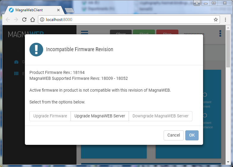
Incompatibility Dialog