8. Operation: Computer Programming
There is a variety of methods and interfaces that can be used to program the TS Series MagnaDC power supply from a computer or programmable logic controller. Standard Commands for Programmable Instrumentation (SCPI) are provided for basic ASCII interfacing without any necessary drivers. In addition, an IVI-COM Driver is included with the installation CD and is available for download from the Magna-Power Electronics web page for more advanced programming requirements. The driver allows the power supply to communicate through many different programming languages and software environments, namely: Visual C++, Visual C#, Visual Basic .NET, Visual Basic 6.0, LabVIEW, LabWindows/CVI, MATLAB, Measure Foundry, and Agilent VEE Pro. Refer to Section 5.7, “IVI-COM Driver” for further details.
TS Series MagnaDC power supply purchased with optional LXI TCP/IP Ethernet (+LXI) or IEEE-488 GPIB (+GPIB) interfaces have additional commands and programming instructions.
8.1. Communications Validation
It is import to establish and validate basic communications functions before starting a sophisticated computer interface project. The following instructions are intended to help customers isolate problems with computer settings, wiring, and electrical noise. The validation instructions also provide a common environment for which Magna-Power can reproduce issues in support cases and better serve the customer.
If not already installed, Magna-Power Electronics recommends using the terminal emulation programs called PuTTY for creating serial connections.
These instructions will validate communications over RS232, but the process can be completed over any interface by adjusting the connection settings. To test, make a physical connection between the RS232 connector on the MagnaDC power supply and the RS232 connector on the computer. Pin outs for these connectors are described in RS232.
Open Device Manager and under ports make note of the COM port number, as shown in Fig. 8.1.
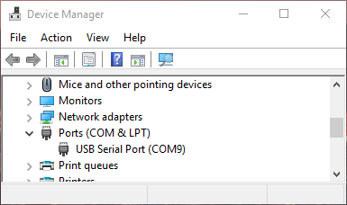
Fig. 8.1 Window Device Manager
Open PuTTY and select the Session menu. Enter the COM port that was found in Device Manger and enter 19200 for the Speed. Set the Connection type to Serial, as shown in Fig. 8.2.
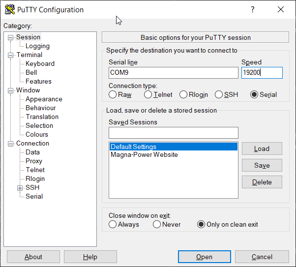
Fig. 8.2 PuTTY Session Settings
Select the Terminal menu and set Force on for all options. Press the Open button to start the communications session with the MagnaDC power supply, as shown in Fig. 8.3.
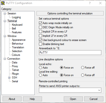
Fig. 8.3 PuTTY Terminal Settings
Session should open a new blank window. Type the command:
*IDN?
If settings match and wiring connections are correct, the session window should look like Fig. 8.4.
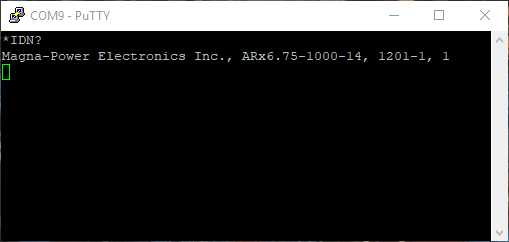
Fig. 8.4 PuTTY Terminal Session Output
8.2. RS232 Communications
One DB-9 female RS232 port comes standard on all TS Series MagnaDC power supply, which provides the simpliest means to communicate with the power supply. All the commands detailed in SCPI Command Set are supported over RS232. Note that LXI TCP/IP Ethernet and IEEE-488 GPIB specific commands will not be available without the respective option.
The RS232 configuration settings are detailed in the following table:
Parameter |
Value |
|---|---|
Baud Rate |
19200 |
Data Size |
8-bit |
Parity |
None |
Stop Bits |
1 |
Flow Control |
Off |
Cable Type |
Straight-through |
Note
When using external converters that utilize the RS232 port, the settings from Table 5.9, “RS232 Interface Configuration” must be used or the product will not communicate.
The RS232 terminal, connector JS3, is detailed in the following table:

Fig. 8.5 RS232 DB-9 female connector included on the TS Series MagnaDC power supply
Pin |
Definition |
|---|---|
1 |
NC |
2 |
RX |
3 |
TX |
4 |
DTP |
5 |
GND |
6 |
DSR |
7 |
RTS |
8 |
CTS |
9 |
NC |
8.3. LXI TCP/IP Ethernet Communications
MagnaDC programmable DC power supply products are available with an optional LXI TCP/IP Ethernet interface (+LXI). The LXI TCP/IP Ethernet interface meets the LXI Class C, Revision 1.4 standard. When specified at time of order, an Ethernet interface module is installed, providing an embedded Ethernet port for communications.
Ethernet connections can be made Magna-Power supplied software interface application, terminal emulation programs like PuTTY, user written software, National Instruments LabVIEW™ and a wide variety of other software programming interfaces.
8.3.1. Address Negotiation
By default, DHCP is enabled on the MagnaDC power supply. If the Ethernet board does not discover a DHCP server, the MagnaDC power supply will default to the Auto-IP configuration as defined in Table 8.3. The device then automatically selects an IP address from 169.254.###.### and subnet as described in RFC 3927 (Request for Comments 3927 - Dynamic Configuration of IPv4 Link-Local Addresses). This routine is used by most computer operating systems.
IP Address |
169.254.###.### |
|---|---|
Subnet Mask |
255.255.0.0 |
Default Gateway |
0.0.0.0 |
DNS Server |
0.0.0.0 |
MAC Address |
01:1E:6F:##:##:## |
Username |
admin |
Password |
leave blank |
The LAN Reset button provides a way to reset the LAN configuration password and to set the device back to DHCP/Auto-IP mode. To activate the LAN Reset function, ensure the power supply is on and in standby mode. Hold down the LAN Reset button for approximately 4 seconds. Observe that the LAN LED rapidly flashes and after 4 seconds, release the LAN Reset button. The LAN configuration password will be reset to blank and the module will be set to DHCP/Auto-IP enabled.
The MAC address consists of two number groups, in format: ##:##:##:##:##:##. For Magna-Power Electronics products, the first three bytes are always 01:1E:6F. The second three bytes are determined by the the LXI TCP/IP Ethernet interface’s serial number, converted to hex. This serial number can be queried from the power supply using the SCPI command SYSTem:COMMunicate:NETwork:SERial.
The LXI TCP/IP Ethernet module supports the mDNS discovery protocol allowing the device to be discovered on the network by software such as National Instruments Measurement and Automation Explorer, Agilent Connection Expert, or the Remote Interface Software supplied with the power supply.
8.3.2. Connectivity
The LAN status LED, located at the rear of the MagnaDC power supply, provides LAN fault and device identification, defined as follows:
- On - Normal Operation
The device has a properly configured IP address and the network cable is connected.
- Flashing - Device Identify
The LXI Device Identification function was enabled via the Instrument Identification web page. This identification can help the user to quickly locate the unit and distinguish it from similar devices.
- Off - LAN Fault
The device is experiencing one or more of the following LAN fault conditions: failure to acquire a valid IP address, detection of a duplicate IP address on the network, failure to renew an already acquired DHCP lease, or the LAN cable is disconnected.
8.3.3. Network discovery
The Ethernet module supports the mDNS discovery protocol allowing the device to be discovered on the network by software such as National Instruments’ Measurement and Automation Explorer, Agilent Connection Expert, or the Remote Interface Software (RIS Panel) supplied with the MagnaDC power supply.
8.3.3.1. NI Measurement and Automation Explorer
To access discovery with NI Measurement and Automation Explorer, the NI-VISA add-on module must be installed along with the standard software package. Start NI Measurement and Automation Explorer, right-click on Devices and Interfaces, and then select “Create New…” Select “VISA TCP/IP Resource” from the list. Click Next and then select Auto-detect of LAN Instrument. Click Next and the software will scan the local network for VXI devices and display them for configuration for further usage with NI-VISA and related software.
8.3.3.2. Agilent Connection Expert
To access discovery with Agilent Connection Expert, start Agilent Connection Expert. Select your computer’s LAN interface and then click the Add Instrument button at the top of the screen. The software will scan the local network for VXI devices and display them for configuration for further use with Agilent VISA compatible software.
8.3.3.3. Web Browser
The LXI TCP/IP Ethernet interface has an embedded web server that allows the user to view and change the module’s network settings. Magna-Power Electronics LXI TCP/IP Ethernet interface is LXI Class C compliant under LXI Standard Revision 1.4.
To access the web server, first determine the module’s IP address via one of the discovery methods described in RIS Panel. Alternatively, if the host computer supports NetBIOS over TCP/IP, you may use the device’s NetBIOS name instead of the IP address.
Open a WC3 compliant web browser such as Google Chrome, Edge (Chromium), or Mozilla Firefox to http:// [ipaddress]/ or http://[hostname]/. The instrument information screen will be displayed as shown in Web interface information panel. This figure provides the basic information about the configuration and allows the user to enable or disable the LXI Identification. Click Enable Identify or Disable Identify to change the state of the LXI Identification. When LXI Identification is enabled, the LAN LED on the back of the MagnaDC power supply unit will blink. This can help the user to quickly locate the MagnaDC power supply and distinguish it from similar devices.
To change the Ethernet interface’s network settings, click the Configure tab in the upper right. The browser will prompt for a username and password if you have not authenticated the device already. To authenticate, enter admin for the username and leave the password field blank. The instrument configuration screen, Web interface configuration panel, will appear. This page enables the user to change the Hostname (which corresponds to the NetBIOS name), the description, password, and TCP/IP configuration. After changes to the configuration are made, click the Save Config button. The configuration will be saved, the Ethernet interface will reboot and instructions will be displayed for reconnecting to the interface.
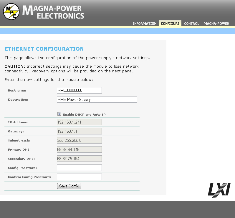
Fig. 8.6 Web interface configuration panel
The browser may prompt for a username and password if you have not authenticated the device already. To authenticate, enter admin for the username and leave the password field blank.
8.3.3.4. RIS Panel
Remote Interface Software describes application and configuration of the Remote Interface Software which is shipped with TS Series MagnaDC power supply. This software provides the user with a quick method to operate a MagnaDC power supply under computer control. The software can be configured for a number of communication interfaces; Ethernet is included as one of these interfaces.
To use the Remote Interface Software with optional Ethernet communications, the address parameters in the Remote Interface Software and that encoded in the MagnaDC power supply must match. The factory default for DHCP is 1 (on) allowing the IP address to be automatically set by the DHCP server on the network. If DHCP is off and the address is unknown, the device can be located using the Remote Interface Software supplied with the MagnaDC power supply. To access discovery, press Find Device in the Communication Setup menu. The routine scans all the devices on the network and provides their addresses and identifications. Select the desired device and press OK; this automatically changes the address in the Communication Setup. The same result can be achieved with a double click on the desired device. After communications is established, the address of the device may be changed by pressing Change Device’s Settings.
8.4. IEEE-488 GPIB Communications

Fig. 8.7 IEEE-488 GPIB connector and pin layout
MagnaDC programmable DC power supply products ere available with an optional IEEE-488 GPIB interface. When specified at time of order, an IEEE-488 GPIB interface module is installed internally, providing an embedded IEEE-488 GPIB port available for communiations. With two UART ports available, RS232 and IEEE-488 GPIB, the one first receiving communications after power on is the port that is activated. Once activated, the other UART port cannot be recognized unless there has been a period of inactivity for 5 minutes. After this period, a new UART port can be recognized by sending communications. The IEEE-488 GPIB terminal, connector JS4, is detailed in
All of the SCPI subsystem commands in the previous section can be initiated using RS232, optional IEEE-488 GPIB (+GPIB), or optional LXI TCP/IP Ethernet (+LXI) communications.
The IEEE-488 standard defines a method for status reporting. As illustrated in [NEED FIGURE], the reporting method uses the IEEE-488 Status Byte (STB). Three bits of this byte are defined as:
Master Status Summary (MSS) Bit
Event Status Bit (ESB)
Message Available (MAV) Bit
The Master Status Summary (MSS) is an unlatched bit. When the Status Byte Register is read using a Status Byte Register query, bit 6 will be 1 if there are any conditions requiring service.
The STB is masked by the Service Request Enable Register (SRE) to allow the user to mask specific or all events from setting the MSS bit to 1. The MSS bit is obtained by logical OR’ing the bits of the enabled Status Byte Register.
The Event Status Bit (ESB) is set when one of the events defined in the Event Status Register (ESR) [REFERENCE ESR TABLE HERE] has occurred. Like the STB, the ESR is masked by the Event Status Enable Register (ESE) to allow the user to mask specific or all events from setting the ESB to 1.
The Message AVailable (MAV) bit is set to 1 when a message is available in the output buffer.
8.4.1. IEEE-488 GPIB Communications with NI MAX
National Instruments offers Measurement and Automation Explorer (MAX), a Graphical User Interface, as a terminal emulation program for configuring an Interchangeable Virtual Instrument (IVI). MAX is usually installed with one of National Instrument’s Application Development Environments such as LabVIEW, Measurement Studio, or with hardware product drivers such as NI-488 and NI-DAQ.
To operate the power supply with MAX, the instrument must first be located for communications. The following steps describe this procedure.
Run the MAX application program.
In the Configuration window, press the + sign to the left of Devices and Interfaces to view the installed devices.
If there is more than one IEEE-488 GPIB device listed, then select the correct GPIB device.
Press Scan for Instruments on the menu bar and wait several seconds.
At least one instrument should appear under the GPIB controller. If no instruments appear, then refer to [REFERENCE PROGRAMMING GPIB SECTION] to verify the correct setup.
On the menu bar, press Communicate with Instrument. The NI-488 Communicator dialog box should appear.
In the NI-488 Communicator dialog box, press the Configure EOS button. The Termination Method dialog box should appear.
Select the option Send EOI at end of Write. Enter 0 into the EOS byte. Press OK.
Pin |
Definition |
Pin |
Definition |
|---|---|---|---|
1 |
DIO1/Data line |
13 |
DIO5/Data line |
2 |
DIO2/Data line |
14 |
DIO6/Data line |
3 |
DIO3/Data line |
15 |
DIO7/Data line |
4 |
DIO4/Data line |
16 |
DIO8/Data line |
5 |
EOI/End or Identify |
17 |
REN/Remote Enable |
6 |
DAV/Data Valid |
18 |
DAV/Gnd |
7 |
NRFD/Not Ready for Data |
19 |
NRFD/Gnd |
8 |
NDAC/Not Data Accepted |
20 |
NDAC/Gnd |
9 |
IFC/Interface Clear |
21 |
IFC/Gnd |
10 |
SRQ/Service Request |
22 |
SRQ/Gnd |
11 |
ATN/Attention |
23 |
ATN/Gnd |
12 |
Shield |
24 |
Gnd |