5. MagnaLINK™
MagnaLINK™ is a low-level high-speed communication protocol designed by Magna-Power Electronics to expand functionality in the presence of multiple products, support real-time control, and handle multi-processor firmware upgrades.
5.1. Network Overview
There are three types of communications that the main control processor manages using three independent ports. On Port A the processor manages internal processor-to-processor traffic. Connected to this bus is the gate drive processor, which is responsible for power controls and protection. Also connected are the auxiliary power supply processors, which power all other boards, cooling fans, and solenoids. These processors are critical to the operation of the MagnaLOAD electronic load; hence, communications on Port A bus are not exposed. Port B carries product-to-product and the front display processor traffic. The port is exposed through two RJ11 connectors located in the back of the product. Connections to the front display are made internally to the product. Port B is designed to handle more network nodes and has programmable termination resistors to dampen transmission-line effects. When connecting two products use only the Magna-Power Electronics supplied MagnaLINK™ cables. Front display boards are also connected to Port B to support remote-panel operation. Port C connects to external devices such as computers. The port defaults to SCPI protocol on start. Magna-Power Electronics software switches the protocol to MagnaLINK™ which contains the full set of commands available to MagnaLOAD electronic load, is lower overhead, and faster speed.
5.2. Master-Slave Module Operation
When MagnaLOAD electronic loads leaves the factory they are programmed with a fixed voltage, current, and power rating corresponding to the model. When multiple MagnaLINK™ compatible products are connected together, new ratings must be programmed for higher-power operation. If the detected power rating does not match the programmed power rating the product enters into a hard-fault condition. This rating check was added so that if any of the modules in the MagnaLINK™ chain are disconnected or fail, the customer can be notified, and take corrective actions. The instructions that follow explain how to wire slaves modules. The process for removing slave modules is identical to adding slave modules.
All MagnaLOAD electronic loads need to be powered off by moving all front rocker switches into the off position. One MagnaLOAD electronic load will be designated as a master all other MagnaLOAD electronic loads will be slaves. On the master, connect the supplied MagnaLINK™ cable from the RJ11 connector labeled MAGNALINK OUT to the slave connector labeled MAGNALINK IN. Connect the provided red and black cable into the white, MOLEX 1545 Series plug, labeled CURRENT SENSE, in the back of the master and the slave units. After all the described connections have been made, turn on the rocker switches. Instructions for programming new ratings using MagnaWEB are discussed in Reprogramming Product Ratings.
5.3. Master-Slave Multi-Rack System Operation
Multi-rack systems have many nodes connected to the MagnaLINK™ network. To accommodate this extra burden, the communications wiring is electrically isolated and the network traffic is routed between racks. The MagnaLINK Interface Device (MID-M), acts as repeater, where incoming messages originating from the master rack, RACK 1, are parsed and resent to the addressed slave rack, as illustrated in Fig. 5.1.
To configure two racks for master-slave operation, use the included RJ11 cable and wire JT3 in the master rack to JE3 of the slave rack. JE3 is on the Fan Control board located at the top of the rack. Connect another RJ11 cable from JR11 of the master to JT1 of the slave. Master and slaves contain MID-S, which acts as pass-through connections for simplifying master-slave wiring. Finally, connect the red and black CURRENT SENSE cable in RACK 2, SUB 11, to the common-mode choke located in the master, RACK 1, SUB 2. The instructions given for two rack, can be readily applied to addition racks. All cabinets must be grounded together and all CURRENT SENSE cables must connect back to the master rack. Instructions for programming new ratings are discussed in Reprogramming Product Ratings.

Fig. 5.1 Multi-Rack System Diagram
5.4. Reprogramming Product Ratings
At bootup the master detects all the slaves on Port B. If the the product was recently reconfigured for master-slave operation, the fron display panel should show a Invalid Product status message since the programmed power rating does not match the one saved. This can also be confirmed by navigating to the About menu and observing the number of slaves detected.
Install and open MagnaWEB software. When the software handshakes with MagnaLOAD electronic load it will detect the Invalid Product condition and open a product rating dialog, as shown in Fig. 5.2. The dialog shows the programmed product rating followed by the detected product ratings.
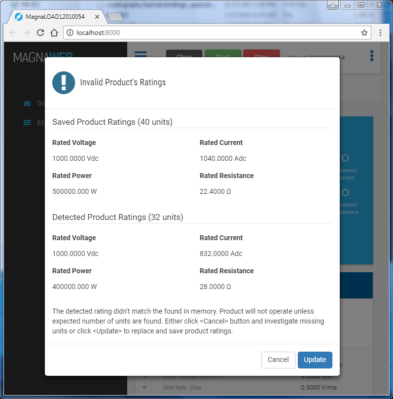
Fig. 5.2 Invalid Product Rating Dialog
Pressing the Update button will copy the detected product ratings into saved product ratings. A progress bar will appear, as shown in Fig. 5.3, the number represents which slave is updating in the chain. Then the progress bar will validate that all MagnaLOAD electronic loads have the correctly modified ratings, then show the completion dialog in Fig. 5.4. Shutdown MagnaWEB and move all rockers switches to their off positions. Wait for at least 5 seconds, then turn on all the loads. On boot, the detected product ratings now match the programmed ratings and normal operation is allowed.
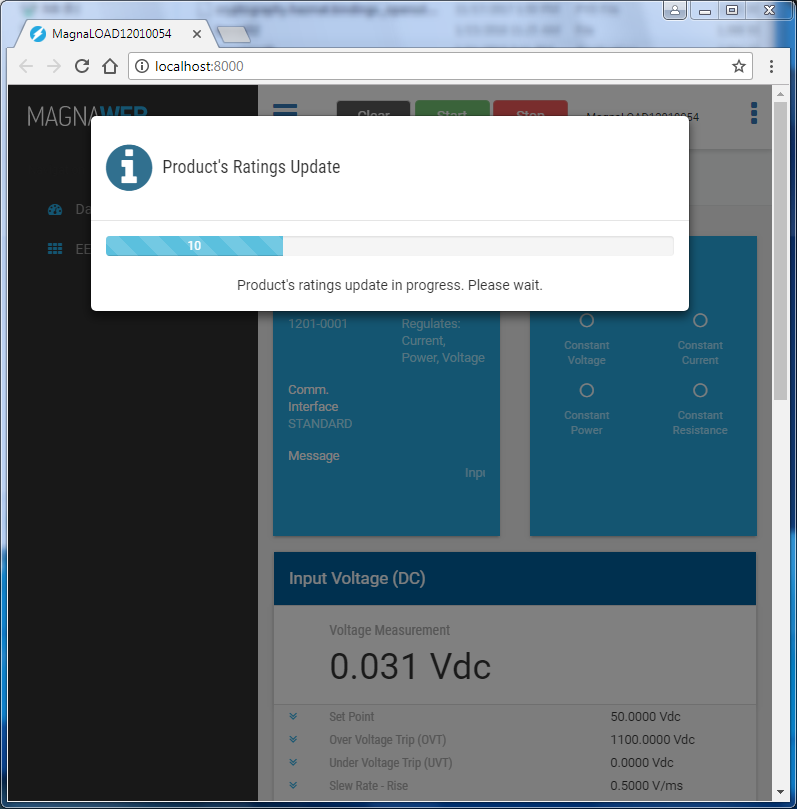
Fig. 5.3 Rating Update Progress Bar
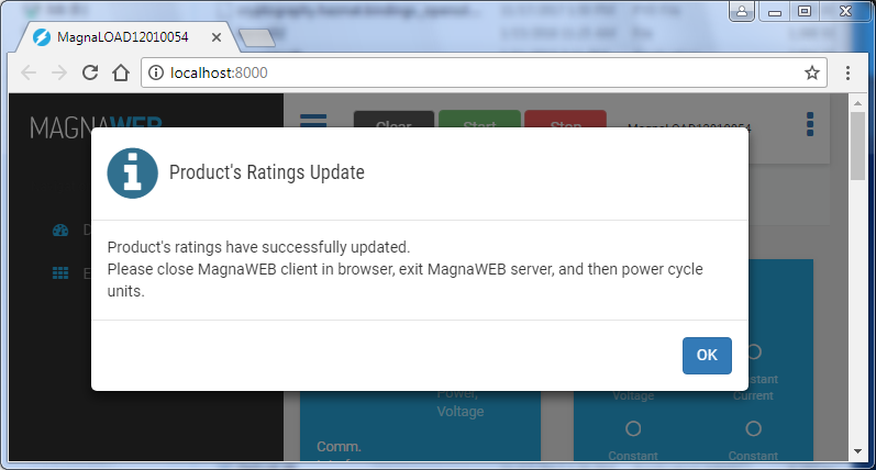
Fig. 5.4 New Ratings Saved