3. Installation
3.1. Inspection
Carefully unpack the MagnaLOAD electronic load and accessories saving all packing materials and included enclosures. Inspect the product for possible shipping damage. Check that there are no broken knobs or connectors, the external surface is not scratched or dented, the meter faces are not damaged, and all controls move freely. Any external damage may be an indication of internal damage. If there is any damage, notify the shipping carrier and Magna-Power immediately.
The following parts are included with all WRx Series MagnaLOAD DC electronic load models:
- WRx Series MagnaLOAD DC electronic load
- USB cable (Type A to Type B)
- USB drive with software, drivers, and digital documentation
- Calibration certificate with Declaration of Conformity
- AC input cable
The following additional parts are included with 12.5 kW WRx Series MagnaLOAD DC electronic load models:
- Rear metal cover with required fastening hardware
- Qty (4) rear support brackets
- Qty (32) 10-32 screws
- Qty (16) 10-32 flat washers and lock washers
3.2. Rack Installation
The 12.5 kW WRx Series MagnaLOAD DC electronic load models are intended for rack-mount installation, designed to fit in a standard 19” equipment rack. When installing into a rack, both front and rear support is required. Fixed rear rack-mount support brackets are provided for the the product’s rear. The unit should be horizontally mounted.
Caution
The WRx Series MagnaLOAD DC electronic load is too heavy for one person to safely lift and mount. To avoid injury, always seek assistance from a co-worker before trying to lift and install the product into a rack.
The following steps, which reference fig-installation-rack-alx, should be followed when installing the 12.5 kW WRx Series MagnaLOAD DC electronic load models into a rack:
- Install 16 clip nuts on the rack frame; 8 for front support and 8 for rear support.
- Install the rear rails onto the MagnaLOAD electronic load, but not the mating rear rail ears.
- While providing support for the MagnaLOAD electronic load, fasten the front ears to the rack using the provided 10-32 screws.
- While continuing to provide support for the MagnaLOAD electronic load, attach the mating rear rail ears onto the rear rails using the provided 10-32 screws. Adjust the position of the rear rail ears to align snuggly with the rear rack rails before tightening.
- Fasten the rear ears to the rack using the provided 10-32 screws.

Fig. 3.1 Rack mount installation diagram for the WRx Series
3.2.1. Cooling Requirements
Water cooling is accomplished through integrated copper microchannel heatsinks. The heatsinks provide a thermal conduction path for heat sensitive components. Water flows through the heatsink chamber to removes heat. Fans are used to circulate air through the inside of the WRx Series MagnaLOAD to prevent hot spots.
Caution
Do not block the air intake on the front of the instrument, nor the MagnaLOAD electronic load’s exhaust. Blocking these vents could cause the product to overheat.
An internal solenoid valve enables water flow when the product’s DC input exceeds 200 watts.
The rack-mount 12.5 kW WRx Series MagnaLOAD provides a 1/2” NPT male inlet and outlet for water connection. For models greater than 12.5 kW, external plumbing interconnects load modules, and a single 1” NPT male is provided at the bottom of the rack for inlet and outlet water connections. For installations utilizing more than one MagnaLOAD, plumbing connections must be paralleled; that is, water should not flow from the outlet of one MagnaLOAD into the inlet of another.
3.3. AC Input Connection
A single-phase AC input connection is used to provide a ground reference and power for the MagnaLOAD electronic load’s fans and control circuits. The AC input power requirements are defined for each MagnaLOAD electronic load on its product rating label. The AC input requirements are further defined in this section.
Connect the provided power cord to the IEC 60320 AC power receptacle on the rear of the MagnaLOAD electronic load. The type of connector used depends on the MagnaLOAD electronic load’s AC input power. For low-power units, an IEC 60320 C13 receptable is used, as shown in fig-installation-power-plug. For high-power units, an IEC 60320 C19 receptable is used, as shown in fig-installation-power-plug-2.

Fig. 3.2 WRx Series IEC 60320 C13 AC power receptacle

Fig. 3.3 WRx Series IEC 60320 C19 AC power receptacle
Note
For WRx Series MagnaLOAD DC electronic load model with AC input type 208SP or 240SP, the utility side is unterminated. The appropriate connector will need to be installed by the user.
Warning
The power cord provides a chassis ground through a third conductor. Be certain that your power outlet is of the three-conductor type with the correct pin connected to earth ground.
Note
For 25 kW to 100 kW models, the AC input voltage is fixed at time of order due to the cabinet fan requirements. 12.5 kW rack-mount models have a universal 1-phase input.
The following tables provides the AC input requirements for the various WRx Series MagnaLOAD DC electronic load power levels:
3.3.1. Ground Connection
Warning
Due to leakage current of models rated 25 kW to 100 kW, the separate facility ground connection must be made to the provided ground stud on the rack.
For the 12.5 kW WRx Series MagnaLOAD DC electronic load models, the system ground is provided by the ground connection on the AC input cable.
For the 25 kW to 100 kW WRx Series MagnaLOAD DC electronic load models, the system ground is provided by attaching the facility ground to the provided 1/4”-20 bolt next to the AC input connector.
3.4. DC Input Connection
Caution
Disconnect AC power from the mains before attempting any installation procedure.
The input of the WRx Series MagnaLOAD DC electronic load is connected to the DC bus by attaching two cables to the input bus bars, as shown in fig-installation-rack-dc-alx. Magna-Power recommends cables be crimped to ring terminals and securely fastened to bus bars using the included 3/8” bolts, washers, and lock washers. The bus bars contain 3/8”-16 threaded inserts. The recommended torque for the DC connection is 240 in-lbf (27.1 N-m). The recommended wire size for different input currents are shown in the table below.
25 kW to 100 kW models are comprised of multiple modules interconnected by a larger bus bars. Additional fastening locations are available on these models to accommodate their increased power ratings. Larger gauge or multiple parallel wires may be necessary for each terminal. For multiple parallel connections, Magna-Power recommends the wires be the same length from end-to-end.

Fig. 3.4 DC input connection for the WRx Series
The following table provides the suggested DC ampacities of AWG (American Wire Guage) copper wire. Paralleled DC cables may be required for larger-ampacity MagnaLOAD electronic load. Ampacity ratings ar based on single conductor in 25 °C ambient free air, with a conductor rated for 60 °C.
Tip
For DC cabling, Magna-Power highly recommends flexible General Cable Carol® Brand Carolprene® cable, used by Magna-Power and many of its customers.
Caution
Make sure DC connections are tightened in accorandance with Magna-Power’s provided torque specification to avoid overheating of the bus bars.
Notes:
- Capacity for AWG wires derived from the National Electric Code. Maximum ambient temperature: 40°C. Maximum wire temperature: 90°C. Continuous duty with wires in free air, not bundled or in conduit.
- Capacity of aluminum wire is approximately 84% of the capacity listed for copper wire.
- For higher current levels, it’s recommended to use bus bars with additional fastening locations allowing for more wire feeds feeds or direct bus bar connection to the load.
A chassis ground reference is also provided on the rear near the DC bus bars, which is tied to the AC input ground. The recommended torque for the ground stud is 55 in-lbf (6.21 N-m).
For rack-mount models, after connections are made, screw the four standoffs into the back panel and place the protective shield over the connections.
For DC bus connections exceeding 315 Adc, Magna-Power recommends multiple runs of 4/0 cabling in parallel. Custom DC bus work may be required to either extend the MagnaLOAD electronic load’s DC bus bars allowing additional DC wire connections, or to make a direct connection with the DC bus work. With increased cable bundling, the ampacity rating of the DC cables will decrease, as less surface area is in free air to cool the wires.
3.4.1. Remote Sense Connection
Remote sensing can improve regulation at a remote reference point. For example, appreciable voltage drop can occur in the wire between the power supply and load as the current increases. By default, the load operates in local sense, where feedback is internally connected to the load’s input terminals. However, the load can also operate in remote sense, and compensate for wire voltage drop by connecting its high-impedance sense wires to the power source terminals. When the remote sense setting is enabled the feedback measurements are taken from the remote sense leads.
The remote sense setting is accessible from either the front panel configuration or by computer command. Magna-Power recommends using 20 AWG wires with the remote sense screw terminals. Connect the MagnaLOAD electronic load’s positive remote sense lead to the positive of the DC source terminals. Connect the MagnaLOAD electronic load’s negative remote sense lead to the negative terminal of the DC source.
Caution
Always ensure that the positive remote sense lead corresponds to the positive DC bus and, likewise, that the the negative remote sense lead corresponds to the negative DC bus. Connecting sense wires with an incorrect polarity can result in equipment damage.
The MagnaLOAD electronic load remote sense implements Smart Sense Detection, which shuts down and protects the product in the event that sense leads are disconnected while live or when the user leaves leads disconnected on start. Remote sense moves the feedback point external to the product. A floating sense connection creates a dangerous open-loop condition.
The MagnaLOAD electronic load protects itself by monitoring both remote an local sense points continuously. When remote sense is enabled, the load will automatically switch from local sense to remote sense only when the input voltage is above 2.5% rated input voltage. The load stays in remote sense mode as long as the voltage difference between remote and local sense measurements are within ±5% of the MagnaLOAD electronic load’s rated voltage. When the load fails to achieve these operating condition, it enters into a soft fault, and displays a remote sense loss message on the front display.
3.5. External User I/O Connection
The WRx Series MagnaLOAD DC electronic load has a 25-pin External User I/O port located in the product’s rear. The External User I/O connector is a standard female D-Sub 25-pin connector. The removable screw-locks provide means of securing mating connectors with commercially available 4-40 threaded hardware. The torque limit for the screw locks is 2 in-lb (0.23 N-m) applied from the mating face side. The maximum push out force is 20 lb-force (89 N) applied from the mating face side.

Fig. 3.5 External User I/O D-Sub 25-pin Connector and Pin Layout
3.6. Computer Connection
This section describes how to connect various communication interfaces to your MagnaLOAD electronic load. Beyond installation, more detailed information about the communication interfaces and programming instructions is described in: Operation: Computer Programming. All available communication interfaces: USB, LXI TCP/IP Ethernet, and IEEE-488 GPIB interfaces operated on a shared bus; only one interface can be active at a time. If none of these interfaces are connected, the MagnaLOAD electronic load defaults to RS485. The active communication interface is denoted in the front panel status menu display.
3.6.1. USB Interface
Universal Serial Bus (USB) interfaces are available on the front (USB2) and the rear (USB1) of the WRx Series MagnaLOAD DC electronic load. Both accept USB Type B connectors and only one is active at a time. A particular port becomes active when a cable is plugged into USB connector and the other end is connected to a powered host. USB2 will always take precedence over USB1.

Fig. 3.6 USB Type B receptacle and pin layout
3.6.2. RS485 Interface
The WRx Series MagnaLOAD DC electronic load supports RS485 communications through a RJ45 connector located on the rear communications panel, as shown in Fig. 3.7. The signals A (Data +), B (Data -), and GND are wired to pins 1, 2, and 7 of the RS485 RJ45 connector, respectively. The remaining pins are electrically disconnected. RS485 interface is always connected provided no other communication interface cables are connected.

Fig. 3.7 RS485 RJ45 receptacle and pin layout
Note
Refer to the ANSI/TIA-568 telecommunications standard for the most common pin-to-pair assignments found on Ethernet cables: T568A and T568B.
3.6.3. Ethernet Interface
The WRx Series MagnaLOAD DC electronic load supports a Ethernet option through a RJ45 connected located on the rear communication panel, as shown in Fig. 3.8. The LXI option activates after receiving its first SCPI command. At that point, the front display panel will show the interface change from either USB1, USB2, or RS485 to LXI. The only way to return to those interfaces is to power cycle the MagnaLOAD electronic load. The LXI TCP/IP Ethernet interface, connector JS5, is detailed in Ethernet Interface.

Fig. 3.8 LXI TCP/IP Ethernet RJ45 receptacle and pin layout
3.6.4. IEEE-488 GPIB Interfaces

Fig. 3.9 IEEE-488 GPIB receptacle and Pin Layout
3.7. Electrical Check
Turn on the MagnaLOAD electronic load using the black control power switch on the bottom left of the front panel. Immediately after turn-on, the MagnaLOAD electronic load undergoes a self-test that check control and input circuitry. The Magna-Power emblem should be displayed during this self-test along with the the word MagnaLOAD electronic load.
Note
After turning the unit on, it will take about 5 seconds for the MagnaLOAD electronic load to initialize before it is ready for use.
When self-test is complete, the Menu display should show the unit’s Standby status, the voltage meter should show whatever the DC bus voltage is, and the current meter should show 0.000. The fans should be running at a low speed.
If the self test fails, the fans do not come on, or the unit fails to come into standby, power off the MagnaLOAD electronic load off and back on with the black power switch. If you continue to have similar issues, contact Magna-Power support for further assistance.
3.8. Firmware Update
Firmware updates are performed through the MagnaWEB software, available for download on the Magna-Power Electronics website. MagnaWEB and firmware are released together, where newer versions of MagnaWEB will sometimes require upgrading the firmware. Firmware is forward upgrading only. Review previous MagnaWEB change logs before replacing firmware, since the older firmware can not be restored. Both forward and backward installation paths are supported for MagnaWEB software. When MagnaWEB establishes communications with the MagnaLOAD electronic load, it queries all board hardware revisions and firmware versions, to determine compatibility. If the MagnaLOAD electronic load is not compatible with the software, the option to downgrade the software or upgrade the firmware is provided, as shown in a pop-up dialog in Fig. 3.10. Before upgrading firmware make sure sources are disconnected and the MagnaLOAD electronic load is is in standby.
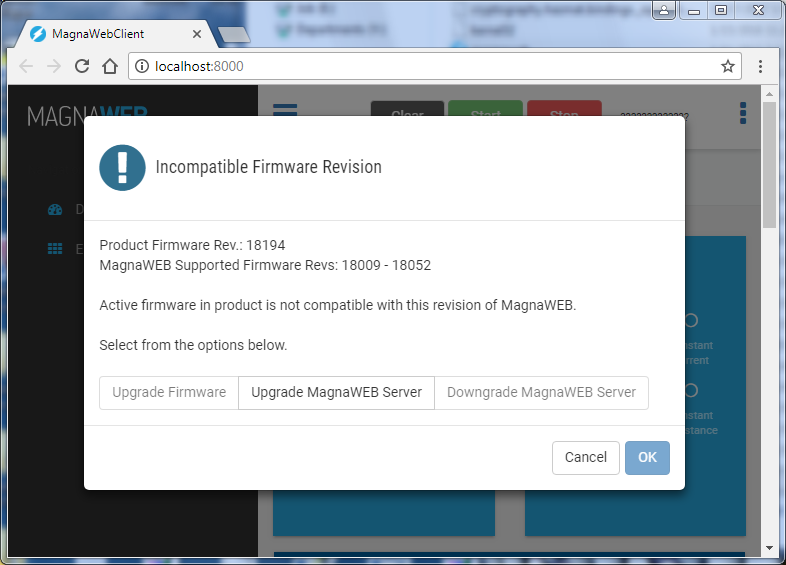
Fig. 3.10 Incompatibility Dialog