

3.8. Water Cooling
Water cooling is standard on Magna-Power’s ML Series DC power supplies and is available as the Water Cooling (+WC) option on the TS Series. In both cases, water chilled below 25°C must be supplied to the power supply’s water inlet. An on-off solenoid controls the flow of water, to ensure chilled water only flows when needed, and prevents condensation buildup. Extensive temperature monitoring through thermal switches directly mounted to heatsinks ensures that power semiconductors do not overheat in the absence of water.
Magna-Power’s water-cooled DC power supplies are built with copper and brass fluid paths; PEX tubing is also used in some cases where a central manifold is used to distribute water to various products or internal assemblies. Because of these metallurgies, deionized (DI) water must not be used—it is highly corrosive to copper and brass, leading to premature wear and damage. Instead, follow the guidelines below to maintain water quality, ensure proper heat transfer, avoid scale buildup, and minimize corrosion or biological growth. These recommendations draw upon Magna-Power’s experience for best practices in water cooling water systems.
Refer to your product’s specifications for recommended maximum pressure and minimum flow rates.
3.8.1. Solenoid Bypass
Magna-Power water-cooled DC power supplies include an internal water solenoid that opens when the heatsink temperature reaches 60°C. This design limits continuous water flow in cooler environments, helping to reduce the risk of condensation inside the power supply. If condensation forms internally, it can damage components or circuitry.
A connector labeled “Solenoid Bypass” is provided so that this temperature-based control can be overridden. Pin 1 is +24V and Pin 2 is the Return. By shorting Pin 1 to Pin 2 while the power supply’s control power is switched on, the user forces the solenoid open, allowing water to flow continuously—regardless of internal temperature.
The same connector reports solenoid state: +24V present indicates that water is not flowing, and 0V indicates that water is flowing.
The connector differs by product series, and the mating half is not provided:
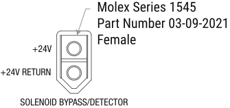
Fig. 3.5 Solenoid bypass connector on TS Series water cooled power supplies
Using the Solenoid Bypass is entirely at the user’s own risk. Continuous cooling flow in low-temperature or humid conditions can cause condensation inside the power supply, leading to corrosion or electrical issues. Damage related to condensation or unapproved cooling practices will not be covered under warranty.
3.8.2. Cooling System Types
Open-loop systems typically draw water from an external source (such as municipal water, a cooling tower, or another reservoir) and then discharge it after use. Ingestion of hard water can lead to scale formation. Scale can impede water flow, coat the interior of copper/brass lines, and cause solenoid valves to seize. Air contact and continuous water makeup can introduce dissolved oxygen, minerals, and biological contaminants, increasing corrosion and biofouling risks. More frequent treatment and monitoring are needed to manage hardness, corrosion, and microbial growth.
Closed-loop systems continuously recirculate the same volume of water through the power supply’s heat exchanger with minimal makeup. Although closed loops are inherently less prone to contamination from outside water, leaks or inadequate pretreatment of makeup water can still introduce hardness, contaminants, or microbes. Closed-loop systems usually operate at low dissolved oxygen levels, which helps reduce corrosion. However, stagnant areas or dead legs can harbor microbial growth. Proper filtration, corrosion inhibitors, and periodic checks are essential to maintain water quality over time.
3.8.3. Water Quality and Treatment
Softened water is generally preferred to reduce hardness. Excess hardness deposits (calcium, magnesium) are the main culprit behind scale plugging small flow paths and solenoid valves. Partially demineralized or RO-permeate blends may be acceptable if they are conditioned with the proper corrosion inhibitors and pH buffers. Avoid pure DI water; it can leach metals from copper/brass and cause severe corrosion.
Keep total hardness (as CaCO₃) under 10 ppm in a closed loop if possible. In open loops, continuous monitoring and chemical treatment are critical to ensure scaling does not occur.
Copper and brass components benefit from azole-based inhibitors (e.g., tolyltriazole or benzotriazole), which form a protective film on copper-based alloys. Mild steel or cast iron piping (if present) can be protected with nitrite or molybdate inhibitors. These also help buffer pH in a closed loop. Regularly test inhibitor residuals and keep them within the recommended ranges provided by your water treatment supplier.
For copper and brass, a pH range of 7.0–9.0 is typically acceptable—going too high can risk localized corrosion on brass, and going too low accelerates copper corrosion. In a closed loop, it is easier to maintain the pH setpoint; in an open loop, you may need continuous monitoring to adjust feed chemistry as water quality fluctuates.
Microbial growth (algae, bacteria, fungi) can form biofilms that impede heat transfer and foster under-deposit corrosion. Apply non-oxidizing biocides periodically (e.g., glutaraldehyde, isothiazolone) or oxidizing products for remedial action (e.g., chlorine dioxide) if microbial counts rise. Consider side-stream filtration and routine draining or flushing of stagnant segments to prevent microbial buildup.
3.8.4. Preventive Measures and Maintenance
Side-stream or in-line filtration helps remove suspended solids that cause fouling or block narrow cooling passages. Aim for 1–5 micron filtration, especially in closed loops, to capture fine particulates. Monitor pressure differential across filters—change or clean filters when differential pressure rises (e.g., 10 psi above baseline).
Schedule annual inspections of the power supply’s cooling path, looking for scale or debris around solenoid valves and fittings. Clean any buildup promptly: flush the system with softened water plus a compatible cleaner, or follow your water treatment supplier’s recommended cleaning and passivation procedure.
In a closed-loop system, track daily or weekly water makeup using a flow meter. Losses beyond expected drift or minor maintenance are a sign of leakage. Excessive makeup in an open loop can rapidly degrade water quality, introducing hard water and contaminants.
Periodically verify flow in all piping segments (including seldom-used branches or bypass lines). Stagnant areas promote corrosion and microbial growth. Consider rerouting or installing a bypass line to keep flow continuous through rarely used piping.
3.8.5. Pressure Monitoring
Magna-Power recommends monitoring inlet water pressure to allow operation only under adequate water supply conditions. Choose a pressure switch that provides a dry contact for a simple permissive, or a pressure transmitter (analog to a controller) if you need visibility and logic. Place the device on the supply line feeding the power supply inlet.
Integrate the signal into the power supply’s Interlock (LOC) so the loop is closed when healthy and opens on fault. With a switch, wire its normally closed contact in series with other safety devices; with a transmitter, have the controller drive a relay that opens the interlock on fault. Commission by recording normal readings at your installation and verifying that simulated low-pressure conditions open the interlock and command a safe shutdown.
Setpoints: Trip thresholds 10–20% above the product’s minimum pressure; optional high-pressure trip at 90–95% of the product’s maximum.
Timing: 0.5–2.0 s running delay before tripping to avoid nuisance events.
Reset: Prefer manual reset; if auto-reset is used, require 5–10 s of healthy readings before re-enable.
3.8.6. Clearing Liquid from Water Path
Before transporting the power supply, ensure that all internal water passages are cleared of residual fluid. To accomplish this, apply control power to the unit, short the Solenoid Bypass connector (thereby opening the solenoid), and use pressurized air (approximately 40 PSI) to blow out any remaining liquid. This precaution helps prevent water from freezing, spilling, or causing corrosion during transit.
3.8.7. Cleaning Water Path
In the event of a stuck solenoid due to buildup or after prolonged storage, Magna-Power suggests circulating a mild acidic solution to dissolve deposits. The recommended procedure is:
Prepare a 5-gallon container with a solution of 5% acetic acid and 95% filtered water.
Use a small water heater set to its highest temperature and keep the container covered to retain heat.
Recirculate the heated solution through the solenoid for up to 24 hours.
If possible, with control power applied and the solenoid bypass pins shorted, reverse the normal flow direction during the circulation period to help dislodge scale and debris.
Following this method will help restore solenoid operation by removing any accumulated deposits, minimizing downtime and the need for solenoid replacement.