

2.6. Product Diagrams
This section provides diagrams detailing the MT Series front and rear panel layouts and physical dimensions for both power levels, along with the DC output bus configurations by rated output voltage.
2.6.1. 150 kW Models
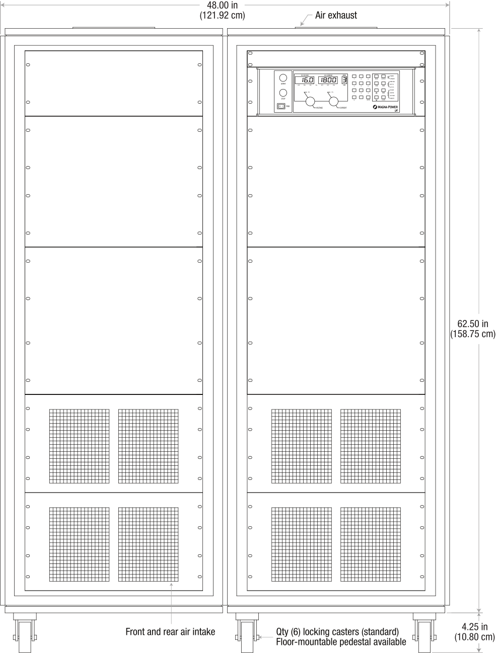
Fig. 2.2 MT Series 150 kW models, front panel layout and dimensions
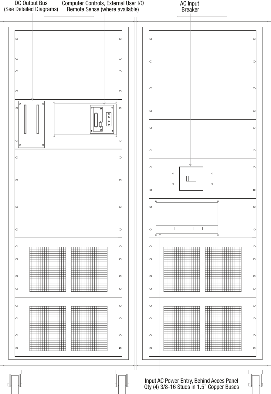
Fig. 2.3 MT Series 150 kW models, rear panel layout and dimensions, showing the DC output bus, the computer control and external user I/O plate, and the AC input breaker
2.6.2. 250 kW Models
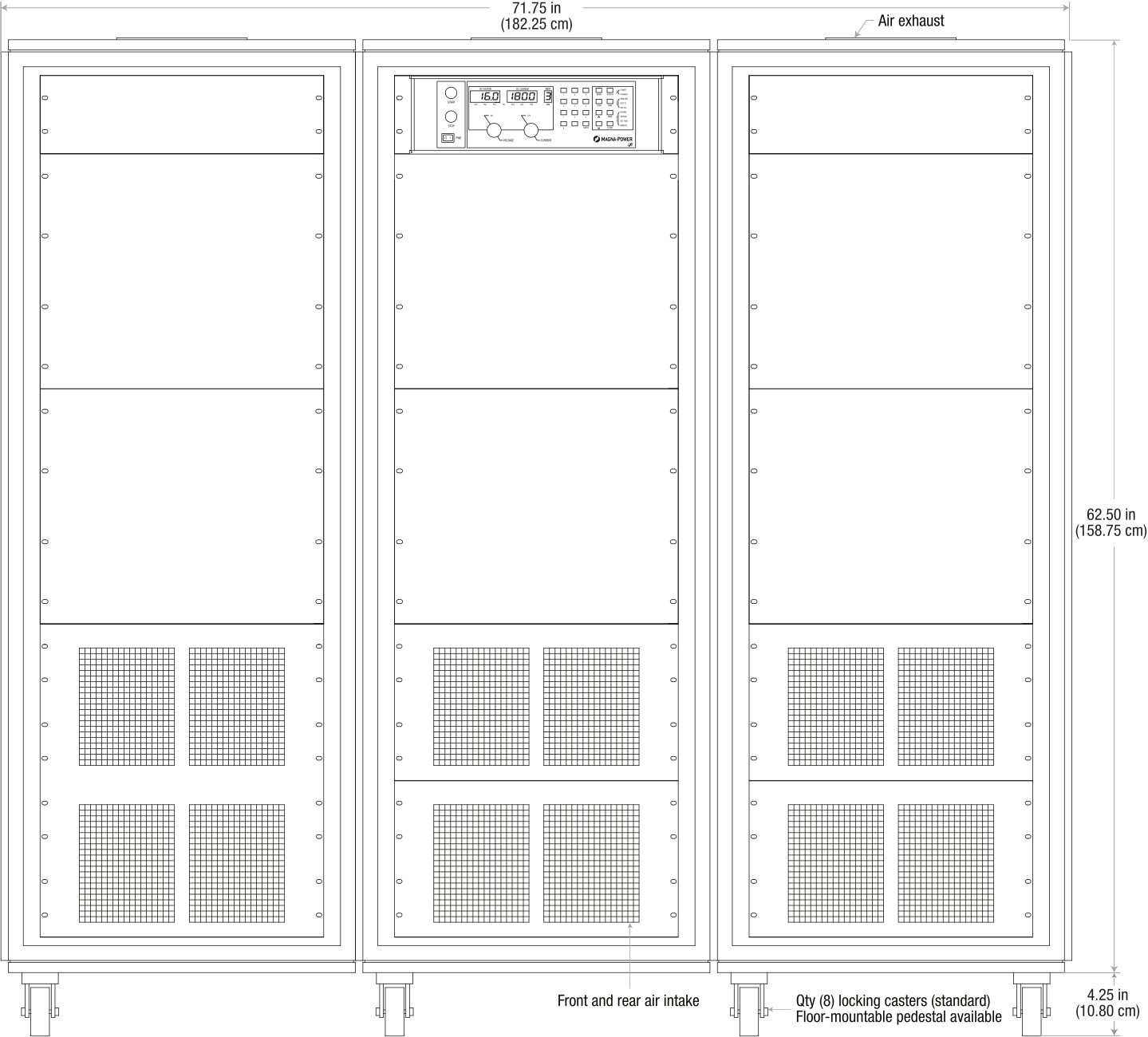
Fig. 2.4 MT Series 250 kW models, front panel layout and dimensions
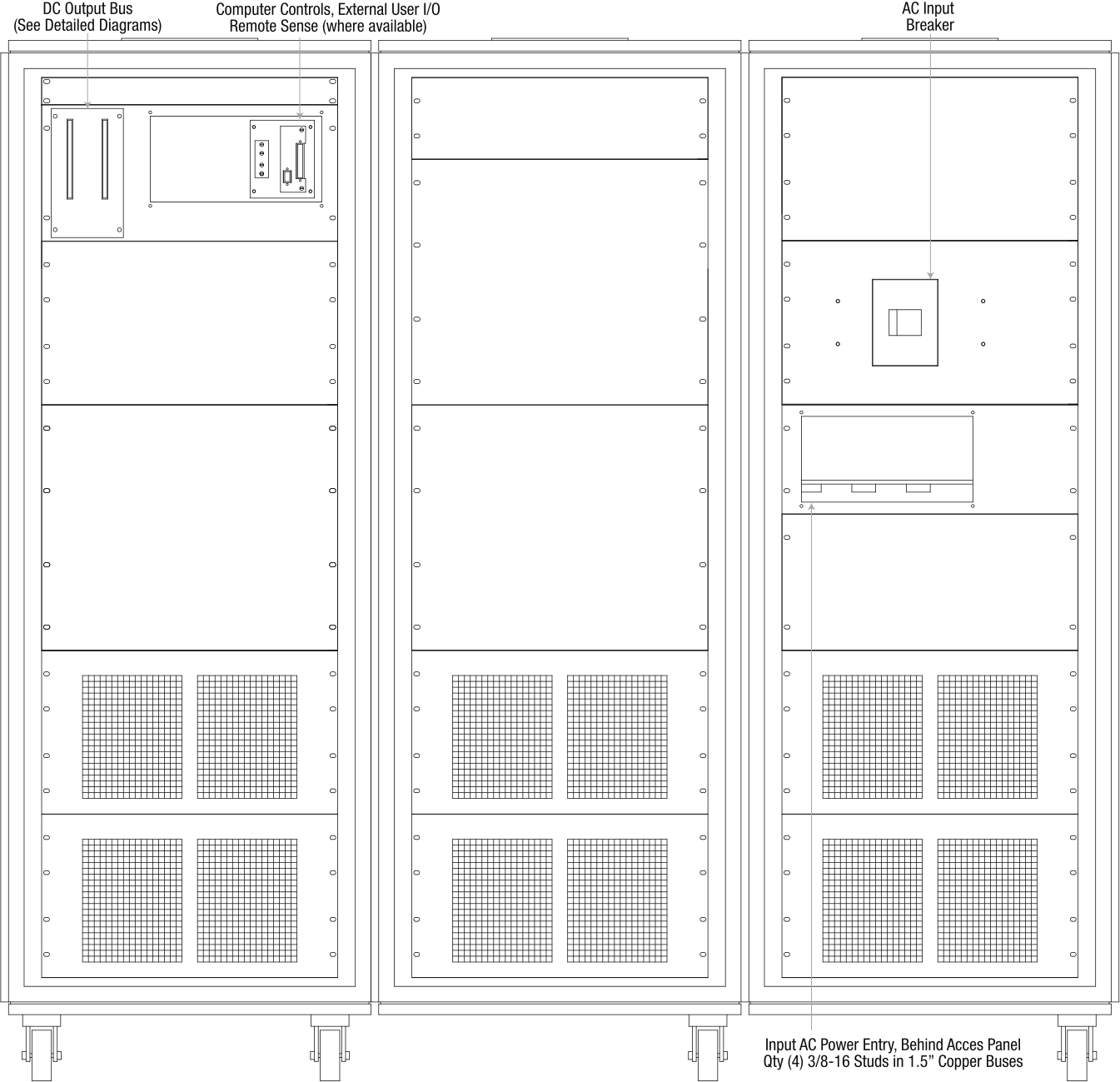
Fig. 2.5 MT Series 250 kW models, rear panel layout and dimensions, showing the DC output bus, the computer control and external user I/O plate, and the AC input breaker
2.6.3. DC Output Bus
The DC output bus configuration varies by the model’s rated output voltage, as detailed in the following diagrams. Mating hardware is included with each output bus. See DC Output Connection for connection instructions.
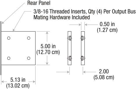
Fig. 2.6 MT Series DC output bus, models rated below 60 Vdc: 3/8-16 threaded inserts, quantity (4) per output bus
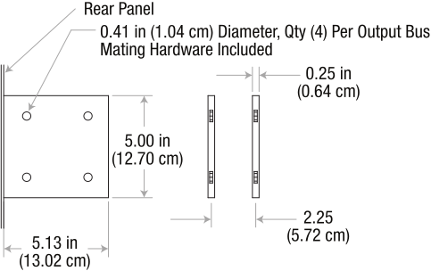
Fig. 2.7 MT Series DC output bus, models rated 60 Vdc through 1000 Vdc: 0.41 in (1.04 cm) diameter, quantity (4) per output bus
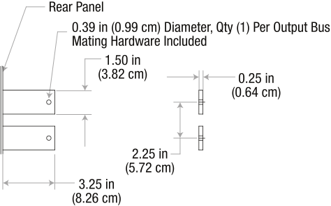
Fig. 2.8 MT Series DC output bus, models rated above 1000 Vdc or with the High Isolation Output Option (+ISO): 0.39 in (0.99 cm) diameter, quantity (1) per output bus