

2.7. Principle of Operation
The MT Series MagnaDC power supply processes power in two stages. An input stage rectifies the three-phase AC mains and regulates a current-controlled DC link, and an output stage inverts that link at medium frequency, isolates it through a power transformer, and rectifies and filters it to produce the DC output. This current-fed arrangement makes the supply tolerant of abusive loads, because the DC link inductors limit the rate of change of current into a fault.
Fig. 2.9 shows the functional arrangement of a single MT Series cabinet. Where a system requires more power than one cabinet delivers, multiple cabinets are operated in master-slave parallel using the UID47 Universal Interface Device, described in Parallel and Series.
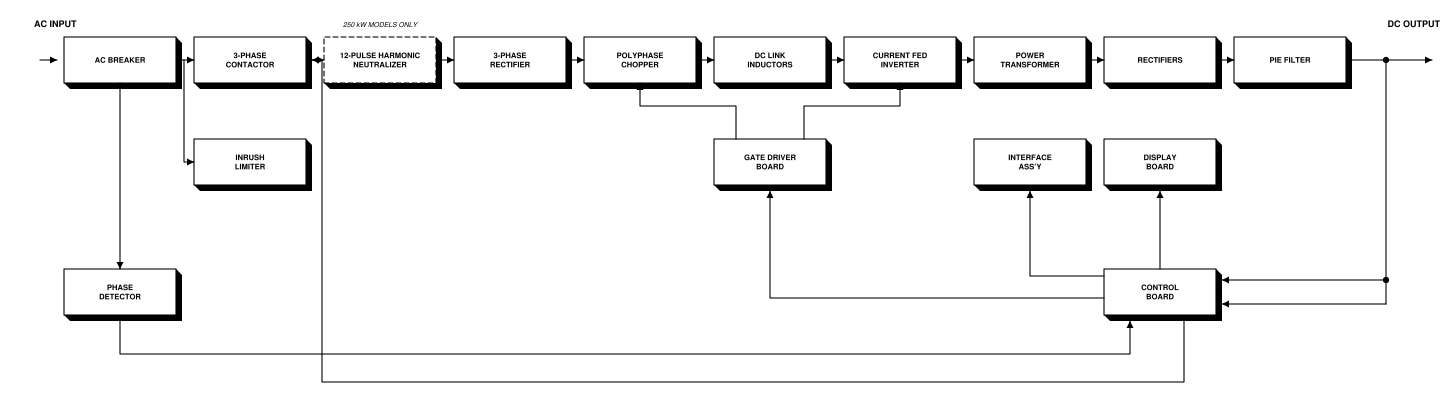
Fig. 2.9 MT Series MagnaDC power supply functional block diagram. The 12-pulse harmonic neutralizer is standard on 250 kW models.
2.7.1. Power Processing
Three-phase AC power enters the cabinet through an integrated AC breaker rated for the full power of the supply. Unlike the smaller MagnaDC products, which protect the power stage with input fuses, the MT Series uses this breaker as both the overcurrent protective device and a means of isolating the unit for service. A three-phase contactor downstream of the breaker makes and breaks the mains under control of the control board, and an inrush limiter charges the DC link through a resistive path before the contactor closes across it, so the supply draws no in-rush current beyond its steady-state rating.
On 250 kW models, a 12-pulse harmonic neutralizer sits between the contactor and the rectifier. The neutralizer multiplies the number of input phases with specially wound magnetic components, cancelling the 5th and 7th harmonic families and leaving the 11th and 13th as the lowest-order input harmonic currents emanating from the supply. Its installation is transparent to the end user. See Harmonic Neutralization for details.
The rectified mains feed a polyphase chopper operating under current-mode pulse-width modulation. The chopper regulates current into the DC link inductors, which present a stiff current source to the following stage. A current-fed inverter switches this link at medium frequency into the power transformer, which provides galvanic isolation and the voltage transformation appropriate to the model’s rating. Operating the isolation transformer at medium frequency rather than at the line frequency is what keeps the magnetics small enough to fit a 250 kW supply into a floor-standing cabinet.
Output rectifiers and a pie-section filter, forming a double-stage LC network, convert the transformer secondary back to DC and reduce output ripple to the value published for the model. A midpoint diode arrangement is used for low-voltage models and a bridge arrangement for high-voltage models.
2.7.2. Control and Monitoring
The gate driver board generates the synchronized modulation for both the polyphase chopper and the current-fed inverter, and reports fault conditions back to the control board. A phase detector monitors the incoming three-phase mains and asserts the phase loss (PHL) diagnostic when a phase is absent.
The control board closes the voltage and current regulation loops using optically isolated feedback amplifiers. Because the feedback path is optically isolated, all user interface circuitry is referenced to earth ground rather than to the negative output terminal, which allows external circuitry to be connected without concern for ground loops or voltage breakdown. The control board also evaluates the protection and diagnostic conditions described in Protection and Diagnostics, and latches a diagnostic condition into memory while disconnecting main power through the three-phase contactor.
Two further boards hang off the control board. The display board carries the front panel meters and indicators for the D Version front panel. The interface assembly carries the 37-pin external user I/O connector, the RS232 connection, and the optional IEEE-488 GPIB or LXI TCP/IP Ethernet connection.