2. Front Panel
The standard XR Series front panel provides local control and display of the product’s various parameters and settings. Fig. 2.14 provides an overview of the XR Version front panel and Fig. 2.15 provides an overview of the C Version XR Series front panel. A lettered list corresponding to the controls and indicators on the front panels is located below the front panel figures.


- Status Indicators
- POWER: Indicates power outputSTANDBY: Indicates control power only
- Function Keys.
- MENU: Selects functionITEM: Selects item within functionV/I DIS: Displays voltage and current set points. Also functions as the up arrow.TRIP DIS: Displays OVT and OCT set points. Also functions as the down arrow.CLEAR: Clears settings or resets faultENTER: Selects item
Voltage and Current Displays. Meters display output voltage, output current, voltage set point, current set point, over voltage trip and over current trip.
Control Power Switch. Power switch energizes control circuits without engaging main power.
Start and Stop Buttons. Engages and disengages main power via integrated mechanical contactor. Pressing the start button energizes the step start and main contactors, followed by enabling of the power processing stages. Pressing the stop button disables the power processing stages and de-energizes the step start and main contactors.
Voltage and Current Knobs. Stepless rotary knob to set voltage and current.
- Diagnostic Alarms
- LOC: InterlockPGL: External input voltage beyond limitsPHL: Under-voltage AC inputTHL: Over-temperature conditionOVT: Over-voltage protection has trippedOCT: Over-current protection has tripped
- Configuration Indicators
- REM SEN: Remote sense enabled. See Remote Sense Connection for more information.INT CTL: Front panel start/stop/clear enabledEXT CTL: External start/stop/clear enabledROTARY: Front panel rotary knob inputEXT PGM: External analog voltage-current controlREMOTE: Computer control
By factory default, the XR Series MagnaDC power supply is configured for local sensing, rotary control, internal control, external control, and voltage input as specified on the rear serial label. XRC Series power supplies cannot be controlled through the front panel other than turning the control power on and off. While in ROTARY configuration, the front panel voltage and current controls set the boundary limits for output voltage and current, respectively. The following sections describe how to use all of the front panel features. Front panel commands are broken into four groups: run mode commands, set point commands, configuration commands, and calibration commands.
2.1. Setting Trip Points
With the product configured for ROTARY input, voltage and current set points are entered with the front panel potentiometers, while over voltage trip and over current trip set points are entered with the up and down arrow keys. Pressing and holding the up or down arrow key causes the set point to change at a faster rate; upon nearing the desired set point, release and press the key again to slow down the rate of change. After a change is made, press the ENTER button to save the new set point or press the CLEAR button to exit without saving. Pressing and holding the CLEAR button for 5 seconds while programming set points resets the over voltage trip and over current trip to their default values. Trip points can be programmed when the product is in either the standby, alarm, or power state. In all control modes, the voltage and current set points can be momentarily displayed by pressing the V/I DIS button and the over voltage trip and over current trip set points can be momentarily displayed by pressing the TRIP DIS button.
2.1.1. Over Voltage Trip
Program the voltage trip setting used to shut the product off with a fault. The product must be in ROTARY set point source to program over voltage trip from the front panel.
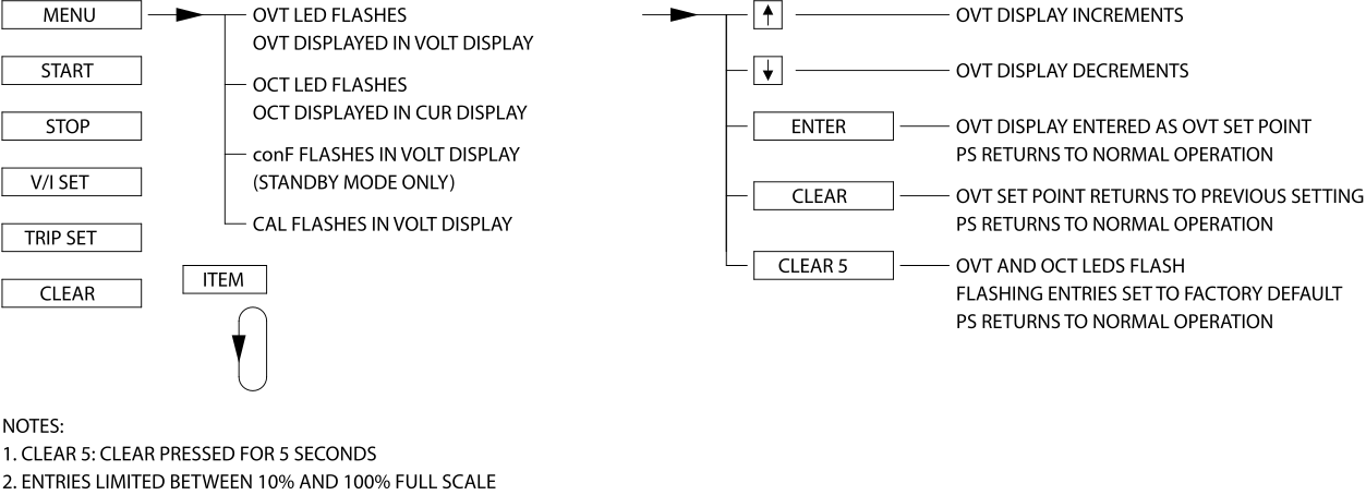
Fig. 2.16 Set the over voltage trip (OVT) from the front panel
2.1.2. Over Current Trip
Program the current trip setting used to shut the product off with a fault. The product must be in ROTARY set point source to program over current trip from the front panel.
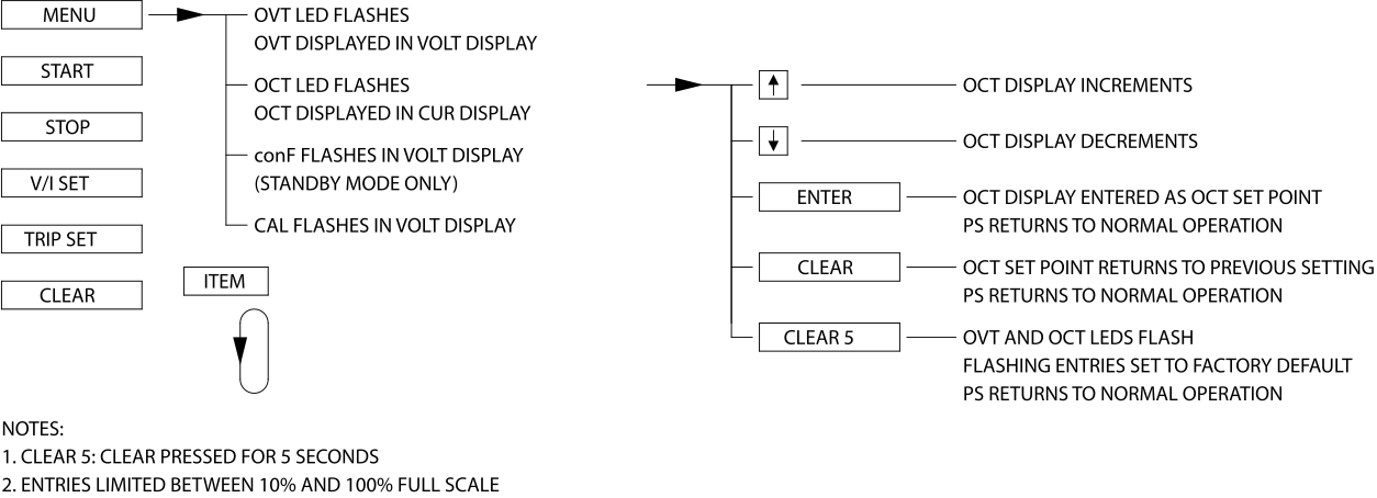
Fig. 2.17 Set the over current trip (OCT) from the front panel
2.2. Configuring Set Point Source
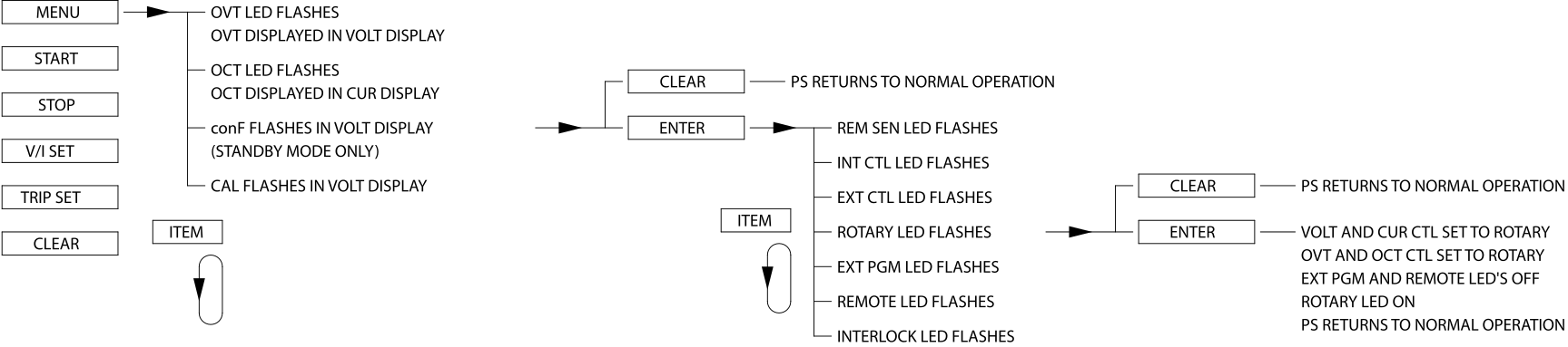
The set point source determines where the XR Series MagnaDC power supply will receive its voltage, current, over voltage trip, and over current trip set points. The instructions below detail how to enable the various set point source configurations. Only one set point source can be enabled at a time.
Note
The product must be in standby or alarm state when configuring the set point source.
2.2.1. Rotary (ROTARY)
Set point control from the front panel knobs.
2.2.2. External Program (EXT PGM)
Set point control from the analog inputs at terminals 3, 22, 4, and 23 of the JS1 external user I/O connector.
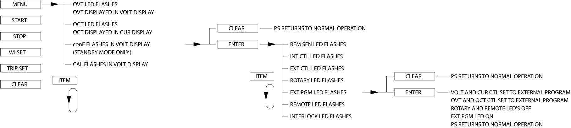
Fig. 2.19 Enable external program (EXT PGM) for external User I/O from the front panel
2.2.3. Remote (REMOTE)
Set point control from any computer interface: RS232, optional IEEE-488 GPIB, or optional LXI TCP/IP Ethernet.
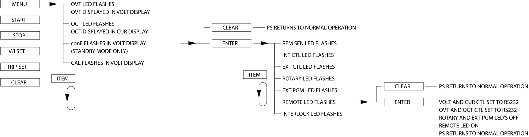
Fig. 2.20 Enable remote (REMOTE) computer programming from the front panel
2.3. Configuring Functionality
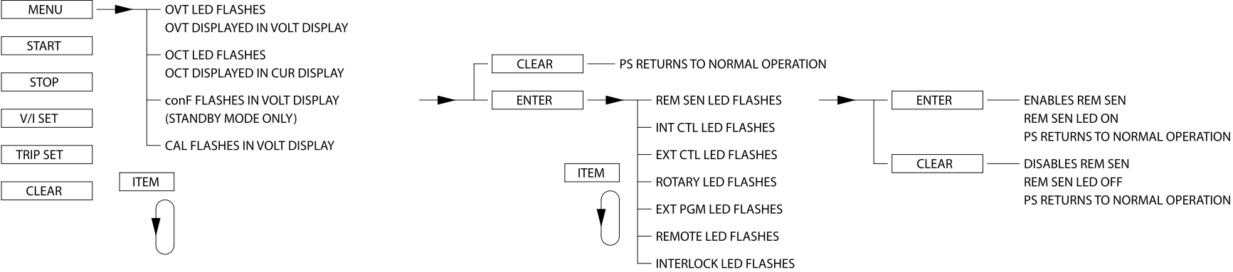
2.3.1. Remote Sense (REM SEN)
Set the product to enable or disable voltage sensing from the high impedance remote sense leads, to provide compensation for voltage drop in the cables.
Note
Remote sensing is only available on models 1000 Vdc and below.
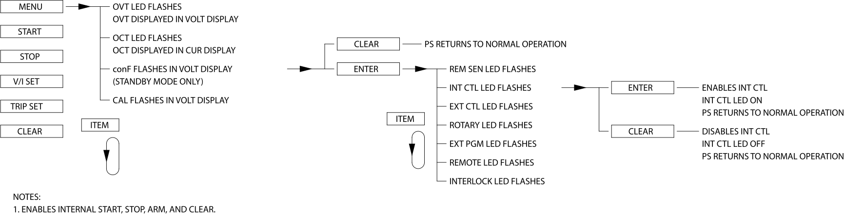
2.3.2. Internal Control (INT CTL)
Allows for front panel control of Start, Stop, and Clear functions.
2.3.3. External Control (EXT CTL)
Allows for digital input control of Start, Stop, and Clear functions at terminals 17, 19, and 18 of the JS1 37-pin external user I/O connector, respectively.
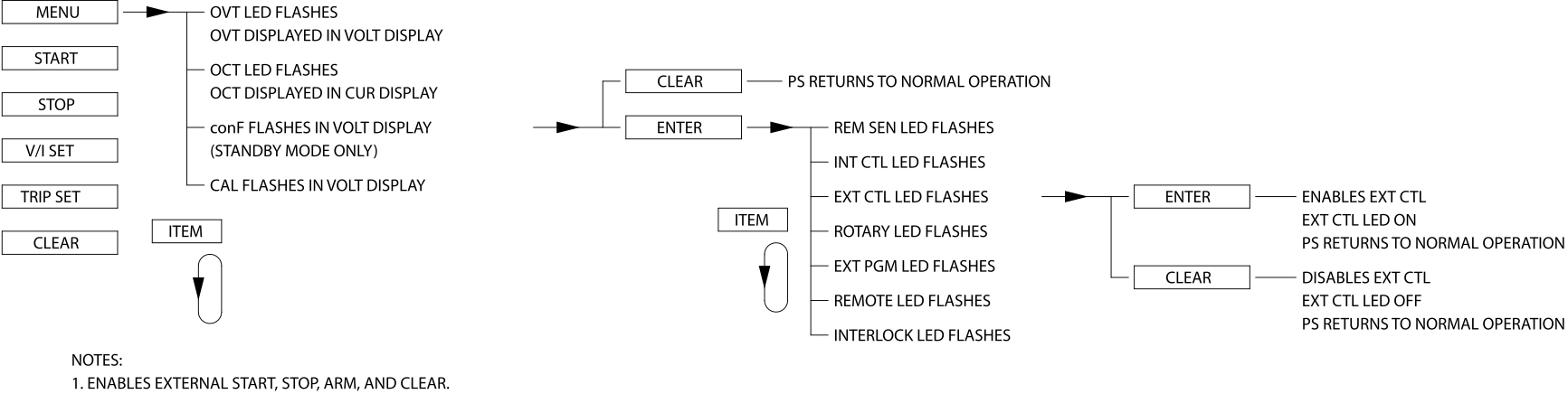
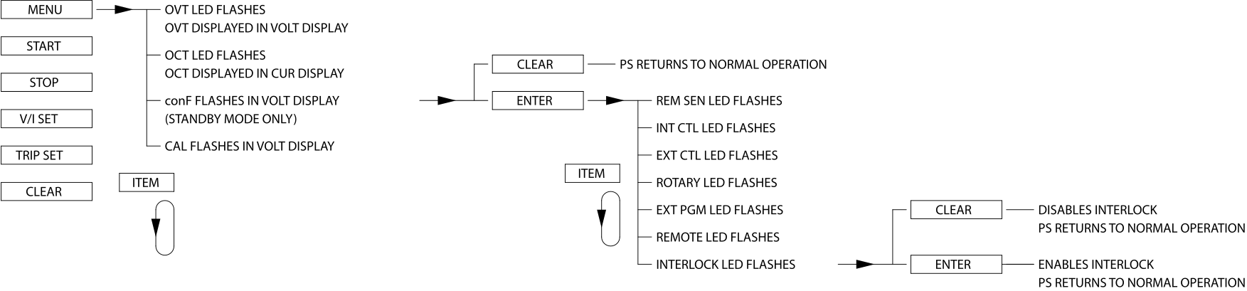
2.3.4. Interlock (LOC)
Enable or disable interlock functionality. Interlock requires a physical short between terminals 26 and 37 of the JS1 external user I/O connector to enable operation.
2.4. Calibration
This section details how to access and change the digital calibration potentiometers from the front panel. For more details on the calibration procedure for the XR Series MagnaDC power supply, refer to Calibration.
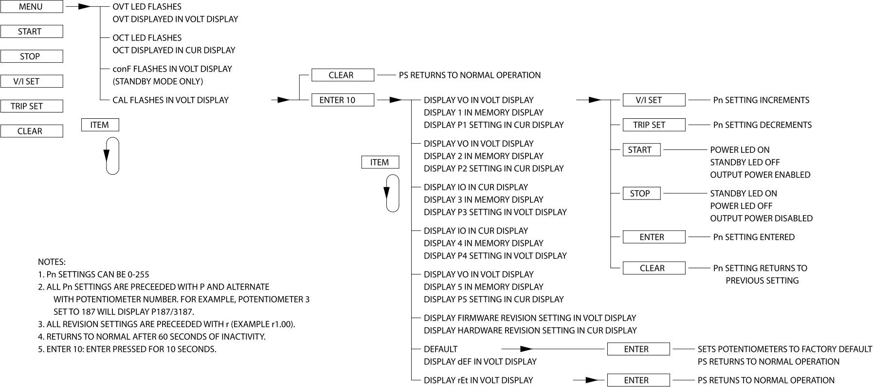
Fig. 2.25 illustrates how to utilize the calibration commands using the front panel. Calibration commands allow calibration of five digital potentiometers, display of the firmware and hardware revisions, and reset the digital potentiometers to the factory calibration settings. All of these commands can be made when the power supply is in either the standby or power mode state.
To enter the calibration commands, first press the menu key. The over voltage trip LED will initially flash. Then press the item key 3 times. The voltage display will flash CAL (calibration). Press enter for 10 seconds or press clear to exit the calibration command menu. Upon entering the calibration commands, the output voltage will be displayed in the voltage display, the potentiometer setting, 0 to 255, will be displayed in the right three digits of the current display, and P and 1 will alternately flash in the left digit of the current display. Potentiometer 1 adjusts the gain of the voltage feedback amplifier, potentiometer 2 adjusts the input offset voltage of the voltage feedback amplifier, potentiometer 3 adjusts the gain of the current feedback amplifier, potentiometer 4 adjusts the input offset voltage of the current feedback amplifier, and potentiometer 5 adjusts the gain of the reference which is used for the digital to analog and analog to digital converters.
Pressing the item key advances control to potentiometer 2. The left digit of the current display will alternately flash P and 2, the output voltage will be displayed in the voltage display, and the potentiometer setting, 0 to 255, will be displayed in the right three digits of the current display.
Pressing the item key again will advance the control to potentiometer 3. Now the output current will be displayed in the current display, the potentiometer setting, 0 to 255, will be displayed in the right three digits of the voltage display, and the left digit of the voltage display will alternately flash P and 3.
Press the item key again will advance to control potentiometer 4. The left digit of the voltage display will alternately flash P and 4, the output current will be displayed in the current display, and potentiometer, 0 to 255, will be displayed in the right three digits of the voltage display.
To advance adjustment to potentiometer 5, press the item key again. The left digit of the current display will alternately flash P and 5, the output voltage will be displayed in the voltage display, and the potentiometer setting, 0 to 255, will be displayed in the right three digits of the current display.
Once a digital potentiometer has been selected for adjustment, pressing the up/down keys increments or decrements the potentiometer setting, respectively. To save the new setting, press the enter key or press the clear key to exit the routine. Instructions for the calibration procedure are discussed in Calibration.
After selecting digital potentiometer 5, pressing the item key displays the firmware revision in the voltage display and the hardware revision in the current display. Pressing the item key again displays dEF (default) in the voltage display. Pressing the enter key resets the five digital potentiometers to the factory default settings.
To exit the calibration menu, press the item key until rEt (return) appears in the voltage display. Press the enter key to exit the calibration menu.