

2.7. Principle of Operation
This section provides a general overview of the technology and power processing stages in a Magna-Power Electronics XR Series. Fig. 2.13 provides an visual overview of the power supply’s main power and control stages.
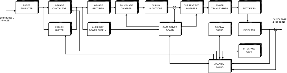
Fig. 2.13 XR Series MagnaDC power supply functional block diagram
Power is fed through AC fuses and is distributed to the auxiliary power supply, inrush limiter, and main 3Φ contactor. The auxiliary power supply operates off the AC mains, supplying power to the other printed circuit boards in the system. The inrush limiter is a step start device which is used to initially charge capacitors on the input DC bus and limit the inrush of current. The inrush limiter is initiated when the power supply is switched from a standby to a power state. After the charge cycle, the main 3Φ contactor is energized and power is allowed to flow to the load. The EMI filter reduces common mode and differential mode noise emanating from the supply.
Output power is controlled through a polyphase chopper. For the 6 kW, 8 kW, and 10 kW XR Series power supplies, three choppers, phased 120° apart, provide a current source to a current fed inverter. The 4 kW XR Series power supplies uses two choppers, phased 180° apart, and the 2 kW supplies uses only one chopper. The choppers are controlled with current mode, pulse width modulation (PWM).
This modulation scheme provides a quick response for transients and filtering harmonics on the DC bus. As illustrated, chopper output current is monitored for balancing and for sensing overload current conditions. The polyphase chopper has been engineered to eliminate harmonic components minimizing currents circulating in the power supply.
The polyphase chopper produces a controlled DC bus which is connected to DC link inductors and current fed, IGBT inverter. The inverter, which operates above 20 kHz, excites the main transformer at higher than normal line frequencies. This operation produces ohmic isolation between the input and output of the power supply using a transformer of dramatically reduced size.
The inverter operates with a 50% duty cycle and its frequency operation is transparent to the performance of the power supply.
The output of the main power transformer is converted to DC via rectifiers. Low voltage versions of the XR Series power supply use midpoint diode configurations and higher voltage versions use bridge configurations.
The DC output voltage is filtered with a pi section filter. This, in combination with the DC link inductors, form a double stage inductive capacitive (LC) filter.
The gate driver board supports a synchronized modulation scheme which integrates power semiconductor switching of the switching power supply, polyphase chopper, and IGBT inverter.
The phase detector senses input line voltage on each phase. Upon detection of a problem, the control board is signaled to shutdown the system. The control board, which is referenced to earth ground, contains optically isolated amplifiers to sense output voltage and current. This circuitry allows the output to be referenced ±1000 Vdc above earth ground.
The display board contains light-emitting diodes for displaying diagnostic conditions and provides an interface for meters and switches.