

1.2. Master/Slave Parallel Operation
Two or more Magna-Power Electronics power supplies can be connected in parallel to obtain a total output current greater than that available from one power supply. The total output current is the sum of the output currents of the individual power supplies. Each power supply can be turned on or off separately.
Master/slave parallel operation permits equal current sharing under all load conditions and allows complete control of output current from one master power supply.
To configure the power supplies for master/slave parallel operation:
Disconnect power to the power supplies and connect all units and loads in parallel as shown in Fig. 1.5.
Remove the cover of the UID and set the jumpers according to Fig. 1.3 (UID46) or Fig. 1.4 (UID47, UID53) for the master/slave parallel configuration. This is the factory default setting. Replace the cover.
Connect a 37-conductor cable from connector JS1 of the master power supply to connector JR2 of the UID.
Connect a second 37-conductor cable from connector JS1 of the slave power supply to connector JR1 of the UID.
Configure the slave power supply for external program (EXT PGM) input. The master unit can be configured for rotary, keypad, external program, or remote input.
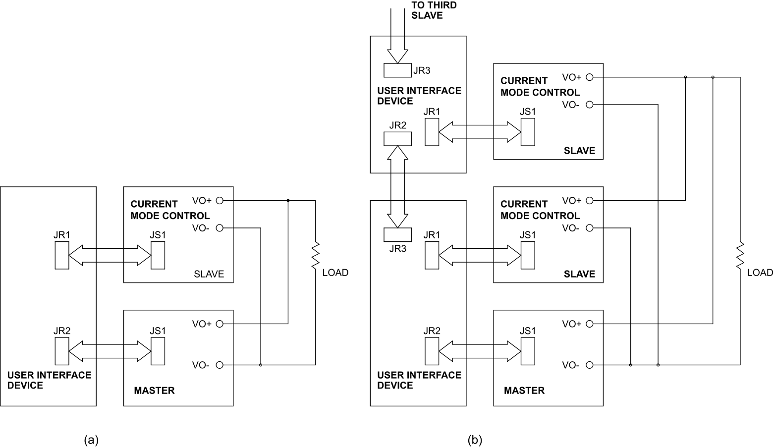
Fig. 1.5 Master/slave parallel connection for (a) one or (b) more slave power supplies
1.2.1. Jumper Functions: UID47 and UID53
For the UID47 and UID53, the master/slave parallel jumper settings perform the following functions:
Jumper connection between JP1 terminals 25 and 26 connects the slave power supplies’ current monitoring outputs, ISO, to the master power supply’s current monitoring input, ISI. This allows the current of all slave power supplies to be summed along with that of the master power supply.
Jumper connection between JP1 terminals 23 and 24 connects the control lines between the master and slave power supplies. Command of the control line is automatically selected with the jumper connections.
Jumper connections between JP1 terminals 1 and 2; 9 and 10; 15 and 16 set the external voltage and current set points to zero. This enables control of the slave power supplies from the master power supply.
Jumper connection between JP1 terminals 11 and 12 connects the power output digital control line of the master power supply to the start digital control line of the slave power supplies. This connection causes slave units to turn on when the master unit is turned on.
Jumper connection between JP1 terminals 13 and 14 connects the standby/alarm digital control line of the master power supply to the stop digital control line of the slave power supplies. This connection causes the slave units to turn off when the master unit is turned off or when a diagnostic condition appears.
Jumper connections between JP1 terminals 3 and 4; 5 and 6; 7 and 8 set the slave voltage trip and over current trip set points just beyond full scale values.
Note
With direct gate driver control, the total output current of the system is always the expected combined value; for example, a two-unit parallel system delivers twice the current programmed on the master. The division of that total between the units, however, may be unequal by up to 5% of full scale. For very high current systems where this imbalance is significant, the UID46 is recommended; in current mode control, the UID46 provides the same transient response performance as the UID47 and UID53. See Selecting a UID.
1.2.2. Jumper Functions: UID46
For the UID46, the master/slave parallel jumper settings perform the following functions:
Jumper connection between JP1 terminals 19 and 20 connects the current monitoring voltage, IO2, on the master power supply to the external current set point input on the slave power supply. This makes the slave power supply operate at the same current output as the master power supply.
Jumper connection between JP1 terminals 11 and 12 connects the power output digital control line of the master power supply to the start digital control line of the slave power supply. This connection causes the slave unit to turn on when the master unit is turned on.
Jumper connection between JP1 terminals 13 and 14 connects the standby/alarm digital control line of the master power supply to the stop digital control line of the slave power supply. This connection causes the slave unit to turn off when the master unit is turned off or when a diagnostic condition appears.
Jumper connections between JP1 terminals 3 and 4; 5 and 6; 7 and 8; 9 and 10; 15 and 16 set the slave voltage set point to maximum and the voltage trip and over current trip set points just beyond full scale values.
1.2.3. Three or More Power Supplies
Three or more parallel connected power supplies can be interconnected by applying additional UID units; one UID is required for every slave power supply. As illustrated in Fig. 1.5 for two slave power supplies, follow the previous instructions plus connect an additional 37-conductor cable from JS1 of the second slave power supply to JR1 of the second UID. Connect a 37-conductor cable between connector JR3 and JR2 of the two UID units. Interconnecting UID units routes master control and monitoring signals to all of the slave power supplies.