

2.4. Dimensional Diagrams
The following are dimensional diagrams for the UID. Click the respective image for a larger view.
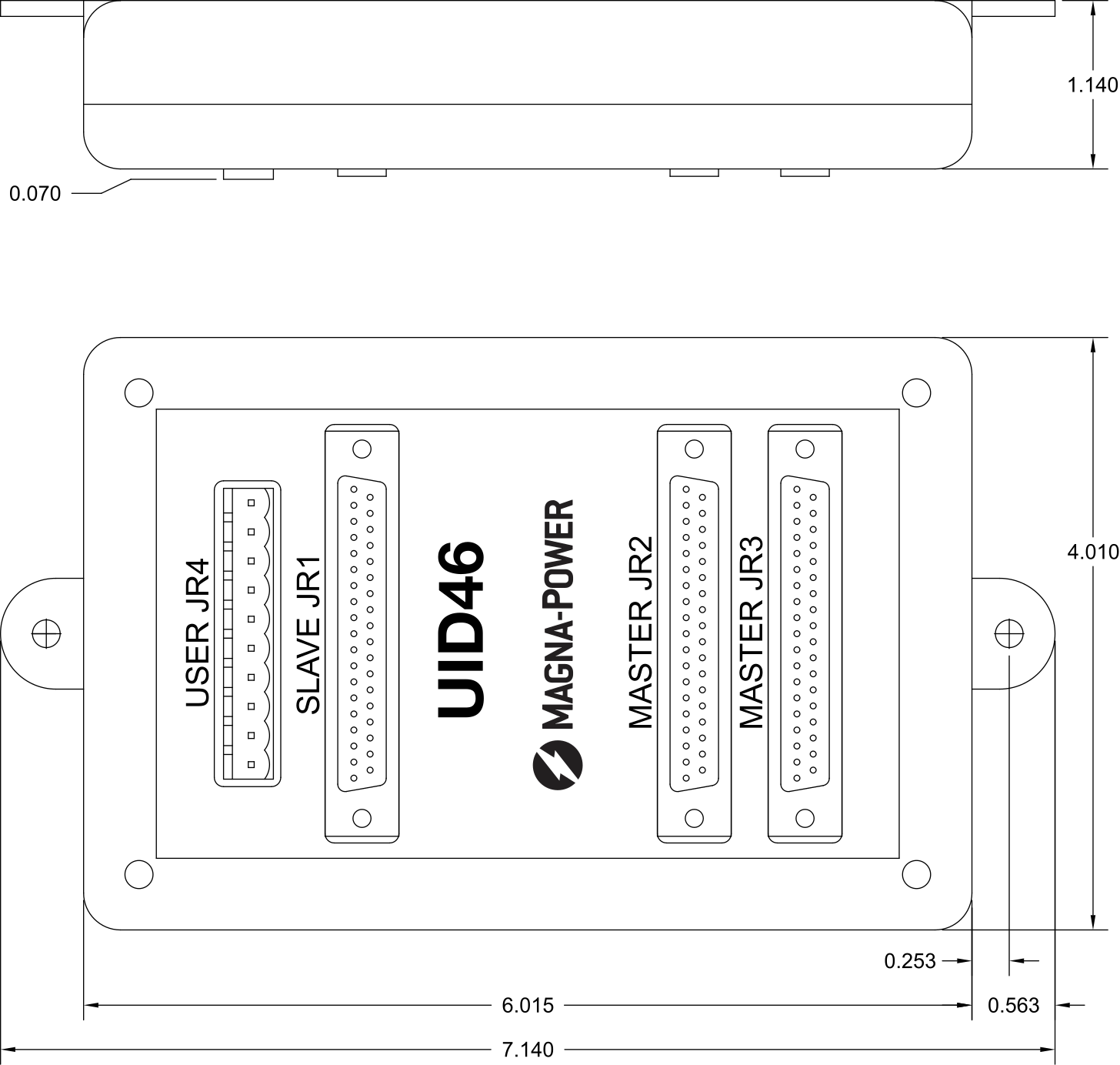
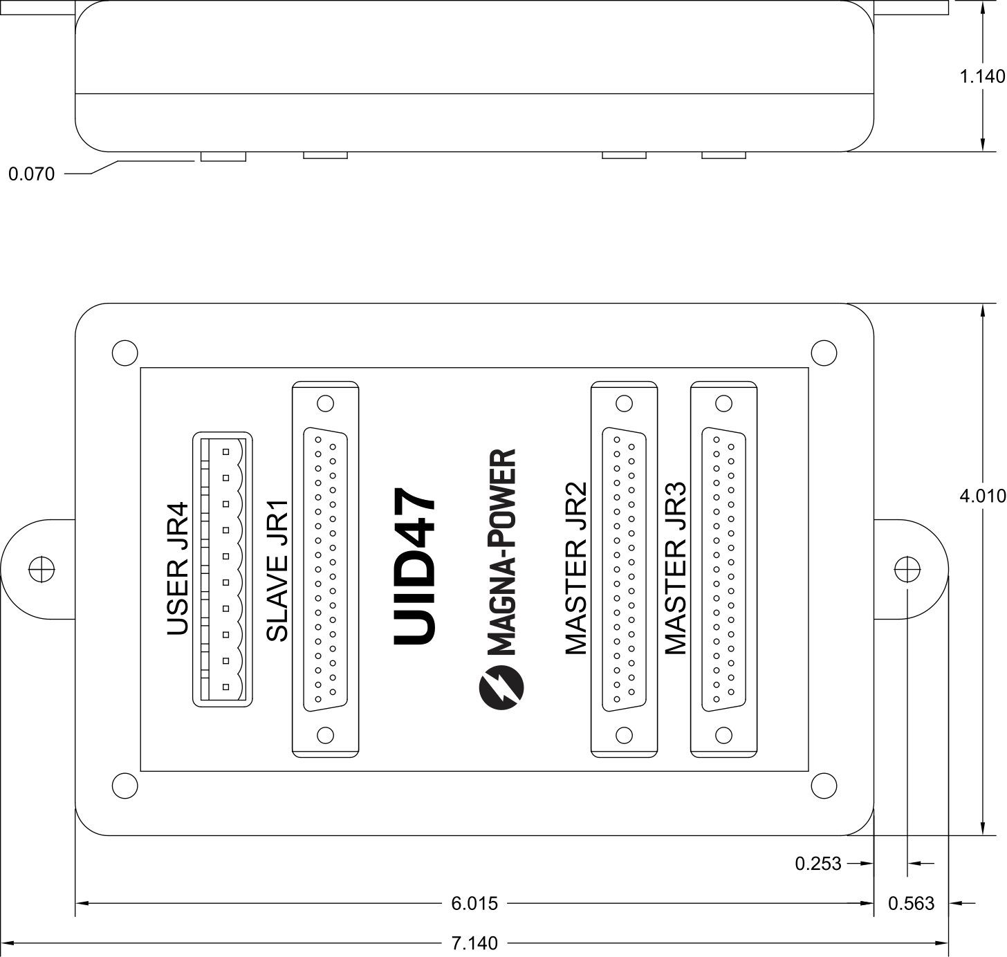
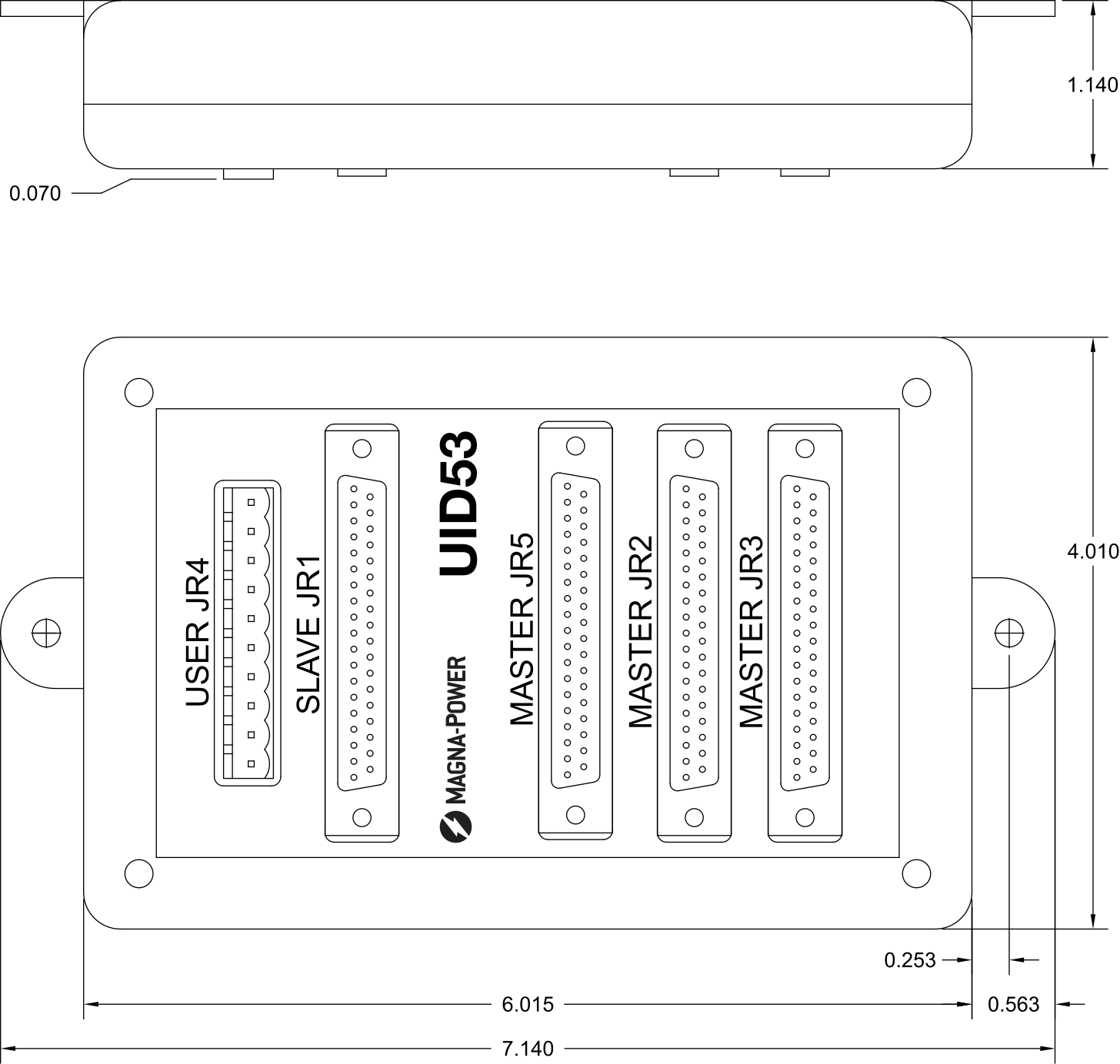
Fig. 2.3 UID53 enclosure dimensional drawing with breakout connector (inches)
2.5. Connectors
Connectors JR1, JR2, and JR3 are 37-pin D-subminiature female connectors. Connector JR4 is a 10-position screw terminal plug connector. The UID53 adds a 37-pin breakout connector, JR5, for BDx and DBx Module integration, used with the included 37-pin to 15-pin interface cable.
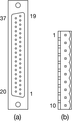
Fig. 2.4 UID connector pin numbering for (a) JR1, JR2, JR3 and (b) JR4, viewed from the UID connector face