

2.6. Product Diagrams
The following diagrams give cabinet dimensions and the location of the user connections for each ML Series power level, followed by the AC input and DC output bus connections. Refer to Cabinet Installation for clearance and access requirements, and to the Physical Specifications above for weights.
2.6.1. 500 kW ML Series Power Supply and Harmonic Neutralizer
500 kW ML Series models combine the power supply and harmonic neutralizer in a single, connected three-cabinet assembly. User AC power connects to the harmonic neutralizer. User-provided water connects to the power supply.
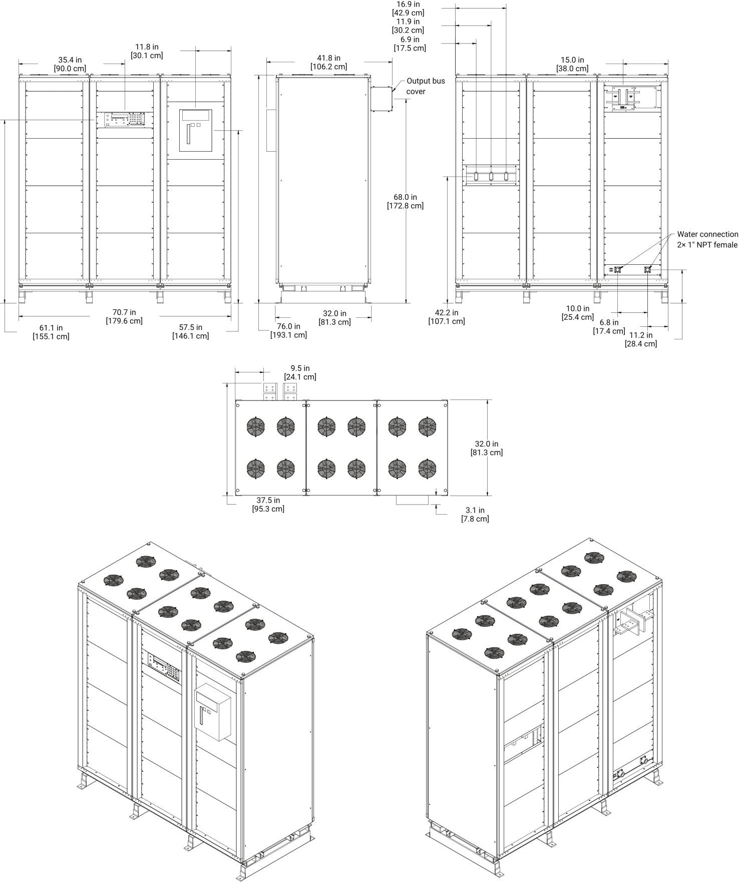
Fig. 2.2 ML Series 500 kW models, power supply and harmonic neutralizer assembly layout and dimensions
2.6.2. 1000 kW ML Series Power Supply
The 1000 kW ML Series power supply spans three standard 19” rack enclosures that are welded together. It ships separately from the 1000 kW harmonic neutralizer, which is positioned to the right of the power supply and joined to it on site as described in Harmonic Neutralizer Interconnection. User AC power connects to the harmonic neutralizer. User-provided water connects to the power supply, with an internal quick disconnect provided for the connection to the harmonic neutralizer.
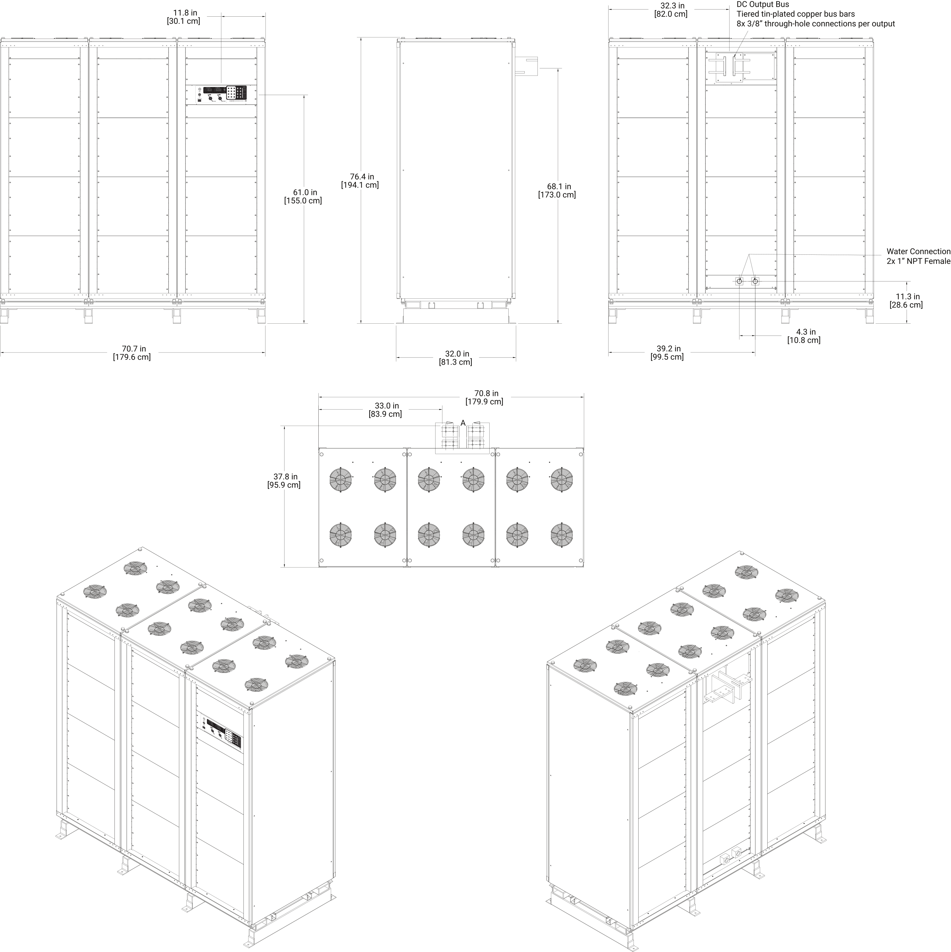
Fig. 2.3 ML Series 1000 kW models, power supply cabinet layout and dimensions
2.6.3. 1000 kW ML Series Harmonic Neutralizer
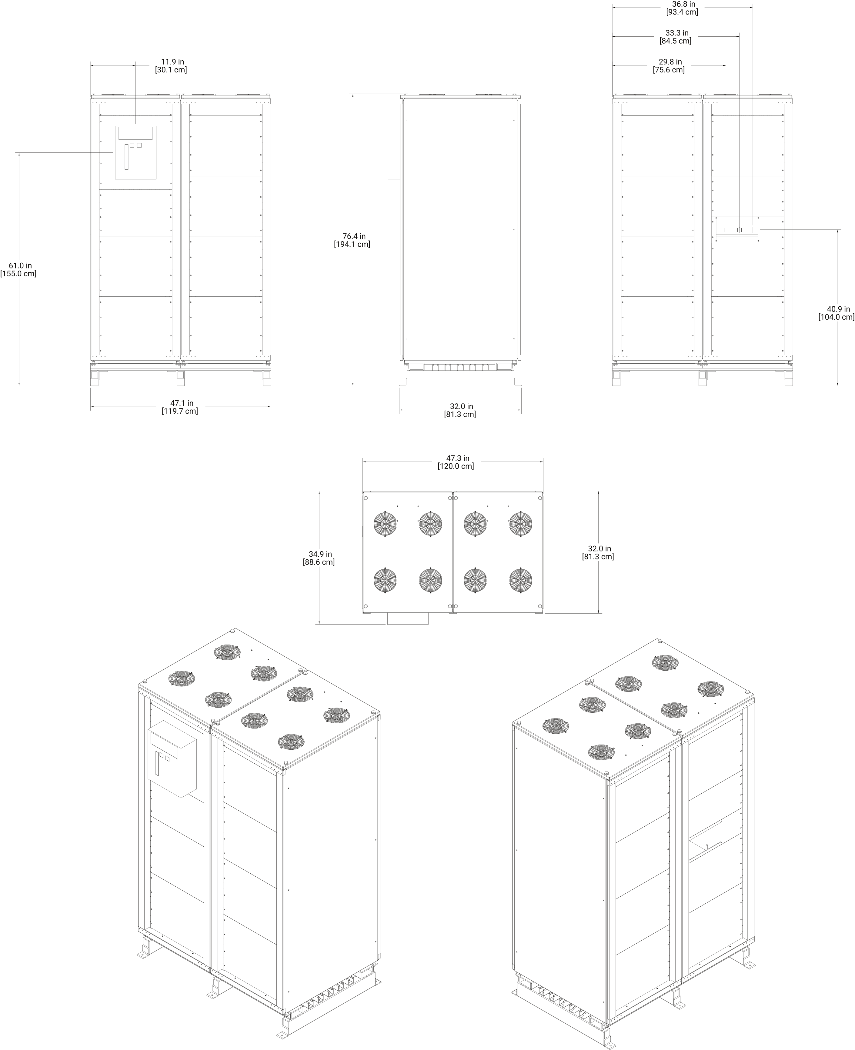
Fig. 2.4 ML Series 1000 kW models, harmonic neutralizer cabinet layout and dimensions
2.6.4. AC Input Power Connections
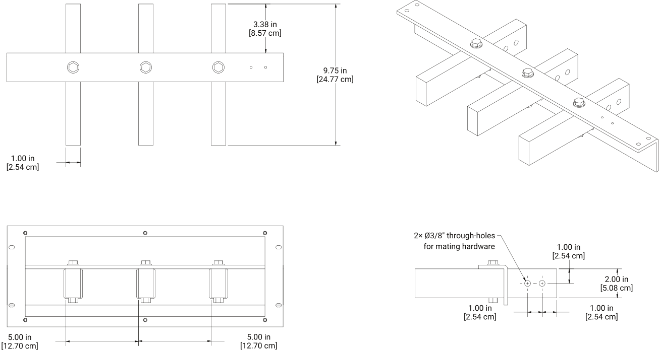
User AC power is connected to three copper bus bars located behind a cover/access panel. Wire should be terminated with a 3/8” ring terminal to mate with the provided mating hardware. The bus bars support wire connections from both sides of the bus bar.
2.6.5. DC Output Power Connections
The DC output bus depends on the model’s maximum DC output voltage rating — the voltage in the model number, not the voltage the supply is set to operate at. The following DC output buses are used on both 500 kW and 1000 kW ML Series models.
2.6.5.1. Models with Maximum DC Output Voltage ≤ 500 Vdc
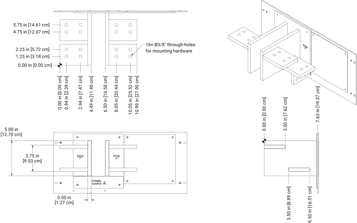
Fig. 2.6 DC output bus for ML Series models with a maximum DC output voltage of 500 Vdc or less
2.6.5.2. Models with Maximum DC Output Voltage > 500 Vdc, ≤ 2000 Vdc
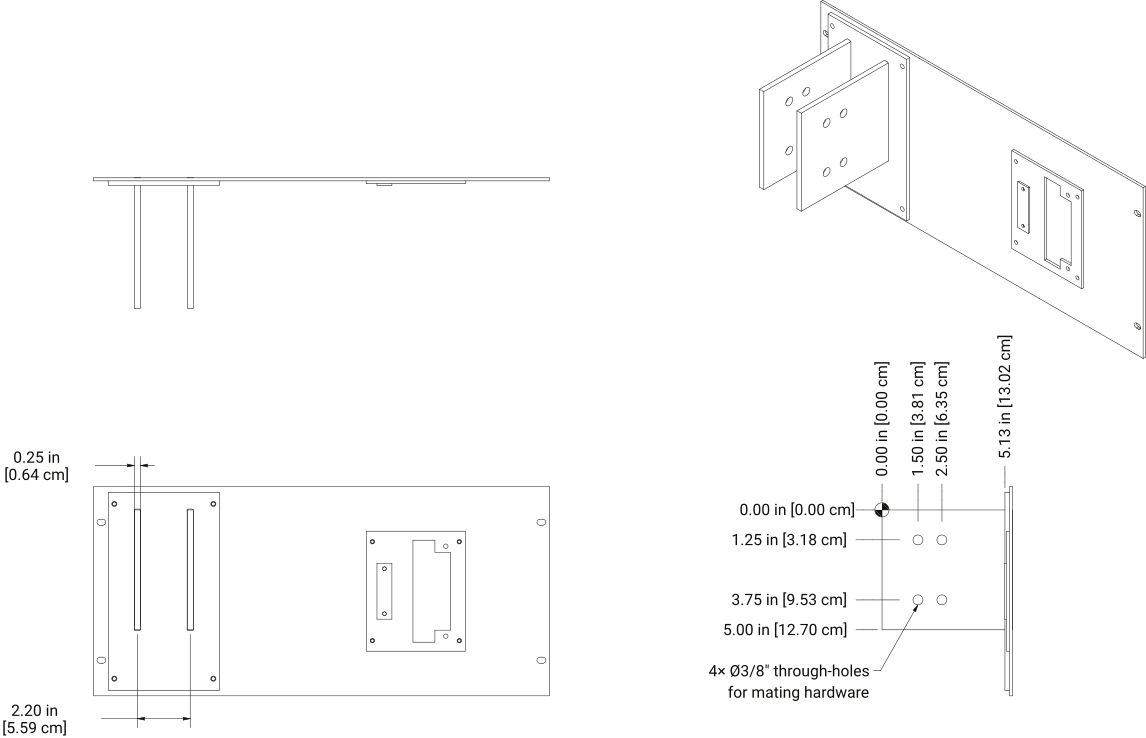
Fig. 2.7 DC output bus for ML Series models with a maximum DC output voltage above 500 Vdc and up to 2000 Vdc
2.6.5.3. Models with Maximum DC Output Voltage > 2000 Vdc, ≤ 6000 Vdc
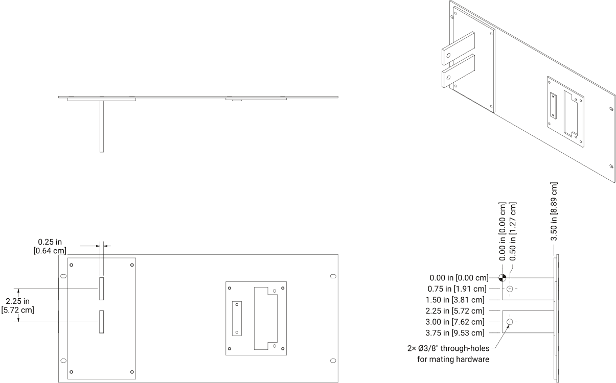
Fig. 2.8 DC output bus for ML Series models with a maximum DC output voltage above 2000 Vdc and up to 6000 Vdc