


Anstiegsrate und die verfügbaren Konfigurationen
Die Anstiegsrate (Slew Rate) definiert die maximale Änderungsgeschwindigkeit pro Zeiteinheit für entweder Ausgangsspannung oder Ausgangsstrom. Die Begrenzungen der Anstiegsrate von Magna-Power erzeugen einen nichtlinearen Anstiegszeiteffekt. Die Anstiegsraten-Spezifikationen von Magna-Power charakterisieren die Anstiegszeit des Netzgeräts als Reaktion auf eine programmierte Spannungs- oder Stromänderung. Die Anstiegsrate unterscheidet sich von der wesentlich schnelleren Transientenreaktion des Netzgeräts, die das Verhalten des Netzgeräts bei einer sprunghaften Laständerung charakterisiert.
Magna-Power bietet zwei Konfigurationen seiner MagnaDC-Netzgeräte an: Standardausgang und High Slew Rate (+HS)-Ausgang. Die MagnaDC-Netzgeräte mit Standard-Ausgangsstufe wurden entwickelt, um die geringstmögliche Ausgangsrippelspannung innerhalb der Grenzen verfügbarer Komponenten, Baugröße und Kosten zu bieten. Ein Teil der Ausgangsstufe besteht aus einer Bank von Aluminium-Elektrolytkondensatoren, die die gewünschten elektrischen Eigenschaften für diese Funktion besitzen. Obwohl das Vorhandensein dieser Komponenten und die daraus resultierende Leistung branchenweit akzeptiert sind, gibt es Anwendungen, bei denen eine geringere Ausgangskapazität mit schnelleren Anstiegs- und Abfallzeiten äußerst wünschenswert und eine höhere Rippelspannung akzeptabel ist. Um diesem Bedarf gerecht zu werden, ist eine High Slew Rate (+HS)-Option verfügbar, die eine Ausgangsstufe mit kapazitätsarmen Folien- und Aluminium-Elektrolytkondensatoren besitzt. Die High Slew Rate (+HS)-Option muss im Werk installiert werden, vorzugsweise zum Zeitpunkt der Bestellung. Nachrüstungen auf die +HS-Option sind möglich, erfordern jedoch den Rückversand des Geräts an das Werk. Tabelle 1 zeigt die verfügbaren Anstiegsraten-Spezifikationen für programmierbare MagnaDC-DC-Netzgeräte bei vollständig ohmscher Last.
| Standard | +HS Option | |
|---|---|---|
| Voltage Slew Rate | 170 ms | 5 ms |
| Current Slew Rate | 200 ms | 10 ms |
Die Anstiegsraten-Spezifikationen gelten für jeden Übergang in Spannung oder Strom. Beispielsweise gilt dieselbe Anstiegsrate für einen programmierten Übergang von 0 auf 50 % Last wie von 0 auf 100 %. Die Anstiegszeit für Spannung und Strom kann mit Gleichung 1 modelliert werden:
wobei `V(t)` die Spannung zu einem bestimmten Zeitpunkt ist, `V0` die programmierte Ausgangsspannung, `t` die Zeit und `T` die Zeitkonstante erster Ordnung (Anstiegsraten-Spezifikation von Magna-Power) in Sekunden.
Zur Veranschaulichung der Anstiegsraten-Spezifikationen wurde ein TSD600-24/208+HS-Netzgerät an eine vollständig ohmsche Last angeschlossen und auf seine Nennspannung und seinen Nennstrom programmiert: 600 Vdc bzw. 24 Adc. Die Ergebnisse dieses Experiments sind in Abbildung 1 dargestellt. Die blaue Kurve zeigt das Stromsignal und die gelbe Kurve das Spannungssignal. Die relative Leistung bezogen auf Nennspannung und -strom ist konsistent mit den in Abbildung 1 gezeigten Ergebnissen für Modelle mit der High Slew Rate (+HS)-Option.
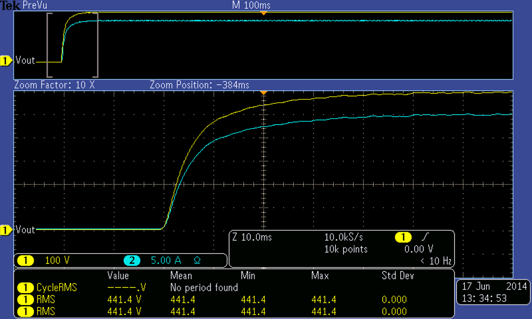
Die neuen Spannungs- und Stromsollwerte wurden dem Netzgerät bei -20 ms vom Ursprung übermittelt. Um zu bestätigen, dass Gleichung 1 mit den experimentellen Ergebnissen übereinstimmt, können wir den ersten großen Zeitabschnitt analysieren, der 10 ms nach Beginn des Spannungs- und Stromanstiegs liegt. An diesem ersten großen Zeitabschnitt beträgt `V0` 600 Vdc, `t` 0,01 s und `T` 0,004 s, da es sich um ein Gerät mit hoher Anstiegsrate handelt. Gleichung 2 zeigt die Auswertung von Gleichung 1, die konsistent mit der gelben Kurve am ersten großen Zeitabschnitt in Abbildung 1 ist.