MT Serie
Programmable DC Power Supply
- Size
- 60U to 90U+
- Power
- 150 kW to 2000 kW+
- Manufactured
- USA
- Build-time
- 6-8 weeks
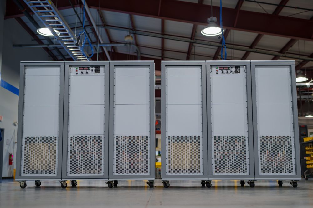
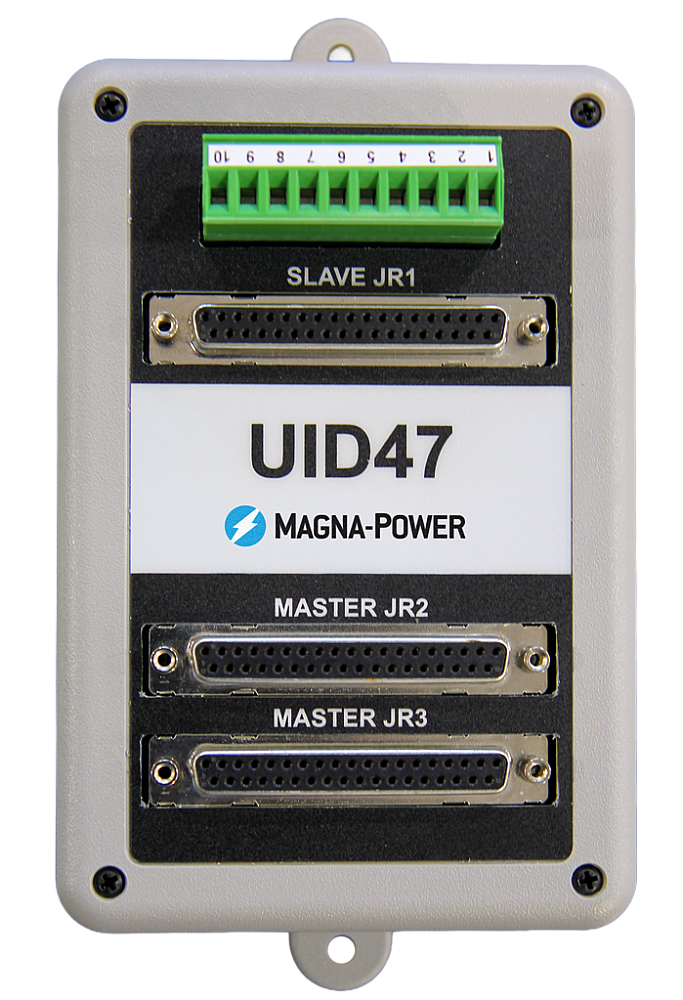
Magna-Power Electronics MT Series uses the same reliable current-fed power processing technology and controls as the rest of the MagnaDC programmable power supply product line, but with larger high-power modules: individual 150 kW and 250 kW power supplies. The high-frequency IGBT-based MT Series units are among the largest standard switched-mode power supplies on the market, minimizing the number of switching components when comparing to smaller module sizes. Scaling in the multi-megawatts is accomplished using the UID47 device, which provides master-slave control: one power supply takes command over the remaining units, for true system operation. As an added safety measure, all MT Series units include an input AC breaker rated for full power.
250 kW modules come standard with an embedded 12-pulse harmonic neutralizer, ensuring low total harmonic distortion (THD). Even higher quality AC waveforms are available with an external additional 500 kW 24-pulse or 1000 kW 48-pulse harmonic neutralizers, designed and manufactured exclusively by Magna-Power for its MT Series products.

Talk with an expert


High-power performance, harmonic control, and configurability for demanding systems
Hochleistungs-DC-Stromversorgung im großen Maßstab
Präzise, stabile Ausgangsleistung für Multi-Kilowatt- bis Multi-Megawatt-Systeme.
Mit einem breiten Spektrum an hohen Strömen und hohen Spannungen bis zu 6.000 Vdc (potentialfrei) liefern die Systeme der MT Serie eine schnelle Transientenantwort, hochgenaue Programmierung und Messung sowie eine geringe Ausgangswelligkeit über einen weiten Leistungsbereich. Mit Konstantspannungs- oder Konstantstrombetrieb und automatischer Überkreuzung reagieren sie schnell auf wechselnde Lasten und halten ihre Sollwerte präzise ein – ideal geeignet für Hochleistungsprüfstände, industrielle Prozessstromversorgung und Multi-Megawatt-Installationen, bei denen Leistung zählt.
Konfiguriert auf Bestellung mit integrierten Optionen
Umfangreiche Standardfunktionen, bei Bedarf erweiterbar.
Wie die gesamte MagnaDC-Reihe beginnen die Netzgeräte der MT Serie mit einer leistungsstarken Steuerungsbasis: SCPI über RS232, isolierte rückseitige User I/O, LabVIEW- und IVI-Treiber sowie Remote Interface Software sind im Lieferumfang enthalten. Darüber hinaus können Sie jedes System mit integrierten Optionen auf seine jeweilige Aufgabe zuschneiden – Hochspannungsisolierter Ausgang (+ISO) für erweiterte Reihenschaltung, Ausgang mit hoher Anstiegsrate (+HS) für schnellere Dynamik, LXI TCP/IP Ethernet (+LXI) und IEEE-488 GPIB (+GPIB) für zusätzliche Kommunikationsschnittstellen sowie Schutz- und mechanische Optionen wie eine integrierte Sperrdiode (+BD) und ein Sockelfuß (+PB) für feste Installationen.

Stufenlose Frontpanelsteuerung mit Blindplatten-Option
Bedienung dort, wo Sie sie brauchen – verborgen, wo nicht.
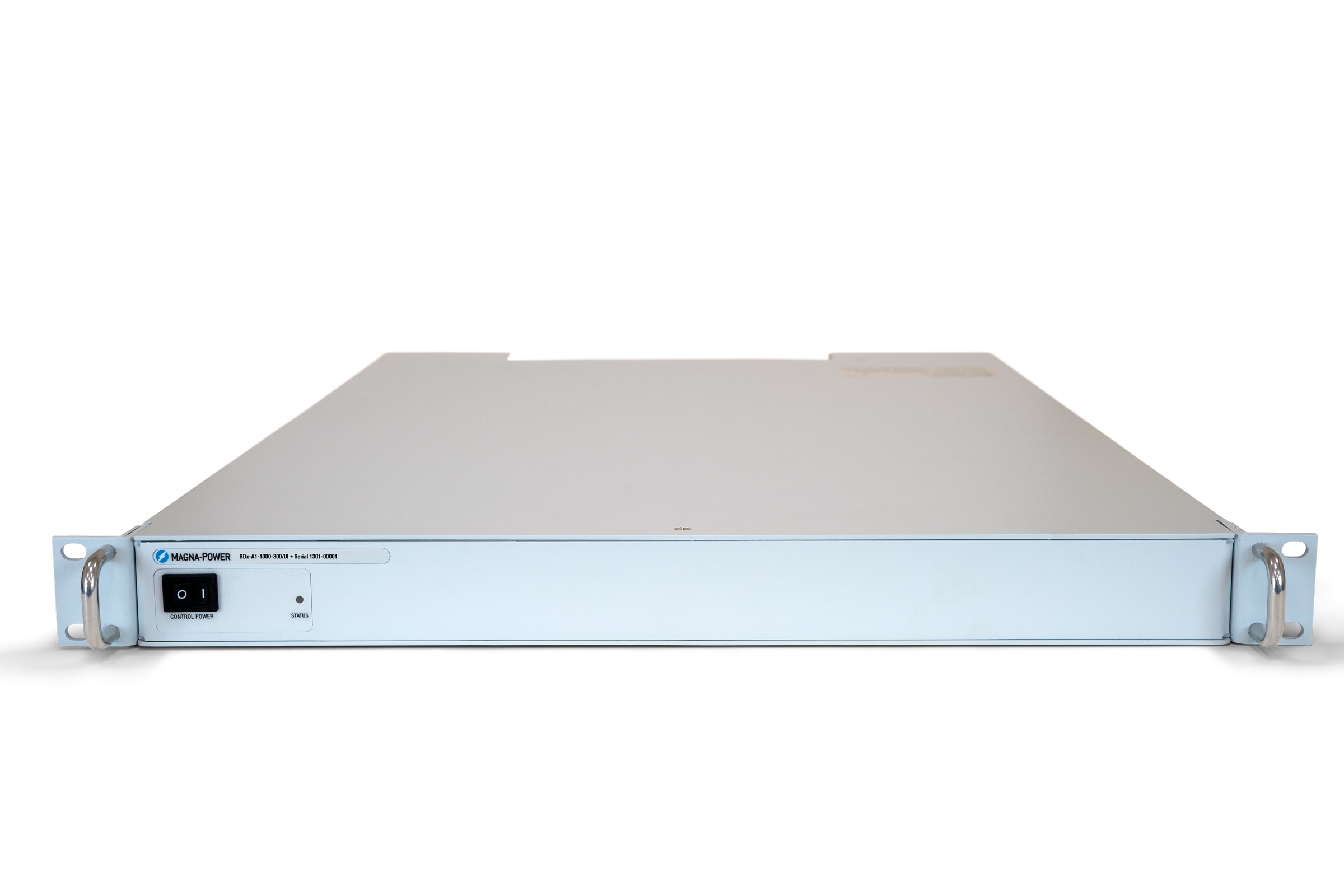
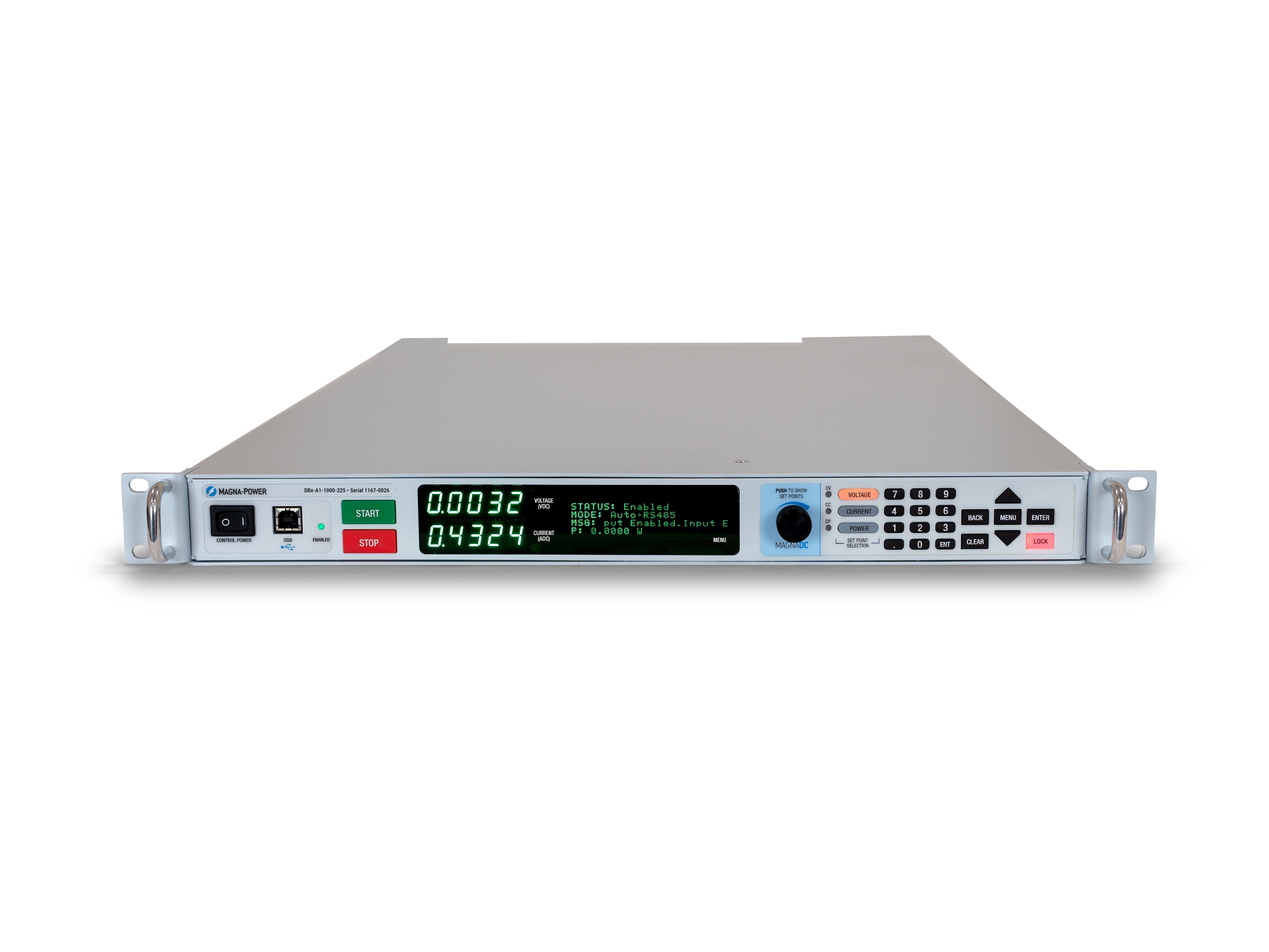
The standard SL front panel provides rotary and key-based control, bright digital metering, and clear status indicators, so operators can configure setpoints, start and stop the supply, and see system health at a glance. For OEMs and production tools, the optional blank (C-version) front panel removes local controls altogether while retaining full control via communication interfaces and rear 37-pin user I/O, keeping systems secure, clean, and operator-proof.
Harmonic Neutralizers für sauberere Hochleistungssysteme
Reduzieren Sie THD an der Quelle für eine einfachere Einhaltung der Netzqualitätsanforderungen.
Oberschwingungen des Eingangsstroms sind ein inhärentes Nebenprodukt von Dreiphasen-Gleichrichtern: Ein standardmäßiges 6-Puls-Frontend erzeugt Oberschwingungsströme beim 1-, 5-, 7-, 11-, 13-fachen… der Grundfrequenz, wobei allein die 5. und 7. Harmonische bei etwa 20 % bzw. 14 % der Grundschwingung liegen. Diese Ströme können empfindliche Lasten anregen – wie Vorschaltgeräte für Beleuchtung mit Reihenkondensatoren/Induktivitäten – und die Einhaltung von Netzqualitätsrichtlinien wie IEEE 519 erschweren. Der zuverlässigste Weg, Oberschwingungsprobleme zu minimieren, ist die Eliminierung der Oberschwingungsströme an der Quelle.
Für Hochleistungssysteme fertigt Magna-Power speziell gewickelte Harmonic Neutralizers, die die Anzahl der Eingangsphasen vervielfachen und den THD des Eingangsstroms passiv drastisch reduzieren. Standard-Magna-Power-Netzgeräte von 1,5–150 kW erzeugen eine 6-Puls-Wellenform, während 250 kW MT Series und 500 kW ML Series Modelle einen integrierten 12-Puls Harmonic Neutralizer und 1000 kW ML Series Modelle einen integrierten 24-Puls Harmonic Neutralizer besitzen – für den Anwender vollständig transparent.

Rugged by design: safety + reliability, as you'd expect from Magna-Power.

Zuverlässige stromgespeiste Leistungsverarbeitung
Robust durch Design: selbstschützende Topologie für maximale Betriebszeit.
The SLx Series uses a high-frequency, current-fed architecture that adds a control stage beyond conventional voltage-fed designs. This topology inherently limits fault energy—avoiding fast-rising current spikes and magnetic core saturation so the supply self-protects and your load stays safe. Paired with state-of-the-art SiC power semiconductors, SLx delivers class-leading power density, efficiency, and reliability, including continuous full-power operation up to 50°C ambient.
- Current-fed architecture with an added control stage vs. voltage-fed.
- Inherent surge immunity—no current spikes or core saturation.
- Self-protecting behavior under fault conditions.
- SiC devices for high density and efficiency; full power to 50°C.
Sicherheitsfunktionen & Verriegelung
Sanftanlauf, programmierbare Schutzfunktionen und eine mechanische Netztrennung für echte Sicherheit.
MagnaDC supplies start gently and watch continuously. A soft-start stage keeps inrush below steady-state draw, while built-in diagnostics monitor line, thermal, and control conditions. In standby or on a diagnostic fault, an embedded AC contactor mechanically disconnects the mains, assuring the unit only processes power when intended. Faults are shown on the front-panel status display, through 5V digital outputs, and are queryable via SCPI.
-
Programmable trips: Over voltage (OVT) and over current (OCT)/
-
Control integrity: Program-line over-voltage detection.
-
Thermal protection: Over temperature on internal heatsinks.
-
Interlock/E-stop fault monitoring as a standard diagnostic.
-
Field integration: 5V interlock input (with 5V reference) for a dry-contact, latching inhibit with control power maintained.
From lab scripts to factory PLCs, flexible programming & integration.
Softwareintegration leicht gemacht
Lesbare Befehle, schnelle Ergebnisse – funktioniert mit jeder Programmiersprache.
MagnaDC-Netzgeräte bieten eine übersichtliche, textbasierte API mit nativem SCPI, einer ASCII-basierten Befehlssprache, die über Socket-Kommunikation gesendet wird. Über 40 gut dokumentierte Befehle decken Start/Stopp, Sollwerte für Spannung, Strom, hochpräzise Messungen und die vollständige Konfiguration ab – so gelangen Ihre Skripte und Systeme schnell vom Proof-of-Concept in die Produktion.
- SCPI-Befehlssätze mit konsistentem Verhalten.
- Start/Stopp & Schutzfunktionen: Ausgang aktivieren, Auslösegrenzen setzen, Status abfragen.
- Hochpräzise Messwerte: Spannung, Strom, Leistung und Sense-Rückmeldung.
- Entwicklerorientierte Dokumentation & Beispiele.
import serial
magnaPower = serial.Serial(port='COM4', baudrate=19200)
magnaPower.write('*IDN?\n'.encode())
print magna_power.readline()
magnaPower.write('VOLT 0\n'.encode())
magnaPower.write('CURR 0\n'.encode())
magnaPower.write('OUTP:START\n'.encode())
magnaPower.write('VOLT 270\n'.encode())
currSetPoints = [50, 100, 150, 250]
for currSetPoint in currSetPoints:
    print 'Setting Current to %s A' % currSetPoint
    magnaPower.write('CURR {0}\n'.format(currSetPoint).encode())
    magnaPower.write('MEAS:VOLT?\n'.encode())
    print magnaPower.readline()
    time.sleep(20)
magnaPower.write('OUTP:STOP\n'.encode())
magnaPower.close()
magna_power = serial('COM4', 'BaudRate', 19200);
fopen(magnaPower);
fprintf(magnaPower,'*IDN?');
idn = fscanf(magnaPower);
fprintf(magnaPower,'VOLT 0');
fprintf(magnaPower,'CURR 0');
fprintf(magnaPower,'OUTP:START');
fprintf(magnaPower,'VOLT 270');
for currSetPoint in [50, 100, 150, 250]
    display('Setting Current to '+currSetPoint+' A');
    fprintf(magnaPower, 'CURR '+currSetPoint);
    fprintf(magnaPower,'MEAS:VOLT?');
    display(fscanf(magnaPower));
    pause(20);
end
#include <stdio.h>
#include <stdint.h>
#include <string.h>
#include <windows.h>

int main()
{
    printf("Opening connection.\n");

    uint8_t recvBuffer[sizeof(uint8_t) * 256];
    memset(recvBuffer, 0, 256);

    // Choose the serial port name.
    // COM ports higher than COM9 need the \\.\ prefix, which is written as
    // "\\\\.\\" in C because we need to escape the backslashes.
    const char* device = "\\\\.\\COM4";

    // Choose the baud rate (bits per second).
    uint32_t baud_rate = 19200;

    HANDLE port = open_serial_port(device, baud_rate);
    if (port == INVALID_HANDLE_VALUE) { return 1; }

    char* scpiCmd = (char*)"*IDN?\n";
    size_t cmdLen = strlen(scpiCmd);
    int result = write_port(port, (uint8_t*)scpiCmd, cmdLen);
    if (result < 0)
        return -1;

    result = read_port(port, recvBuffer, 256);
    printf("Sent: %s\nReceived: %s\n", scpiCmd, recvBuffer);

    scpiCmd = (char*)"VOLT 0\n";
    cmdLen = strlen(scpiCmd);
    result = write_port(port, (uint8_t*)scpiCmd, cmdLen);
    if (result < 0)
        return -1;

    scpiCmd = (char*)"CURR 0\n";
    cmdLen = strlen(scpiCmd);
    result = write_port(port, (uint8_t*)scpiCmd, cmdLen);
    if (result < 0)
        return -1;

    scpiCmd = (char*)"OUTP:START\n";
    cmdLen = strlen(scpiCmd);
    result = write_port(port, (uint8_t*)scpiCmd, cmdLen);
    if (result < 0)
        return -1;

    scpiCmd = (char*)"VOLT 270\n";
    cmdLen = strlen(scpiCmd);
    result = write_port(port, (uint8_t*)scpiCmd, cmdLen);
    if (result < 0)
        return -1;

    char setPoints[4][5] = {"50", "100", "150", "200"};
    char setPointBuffer[40];
    scpiCmd = (char*)"MEAS:VOLT?\n";

    for (int i = 0; i < 4; i++)
    {
        sprintf(setPointBuffer, "CURR %s\n", setPoints[i]);
        printf("Setting current to %s A\n", setPoints[i]);
        cmdLen = strlen(setPointBuffer);
        result = write_port(port, (uint8_t*)setPointBuffer, cmdLen);
        if (result < 0)
            return -1;
        memset(recvBuffer, 0, 256);
        result = read_port(port, recvBuffer, 256);
        printf("Received: %s\n", recvBuffer);
        Sleep(20000);  // 20000ms = 20s
    }

    scpiCmd = (char*)"OUTP:STOP\n";
    cmdLen = strlen(scpiCmd);
    result = write_port(port, (uint8_t*)scpiCmd, cmdLen);
    if (result < 0)
        return -1;

    CloseHandle(port);

    printf("Connection closed.\n");
    return 0;
}
using System;
using System.IO.Ports;
using System.Threading;

namespace SerialCommunicationInCSharp
{
  public class Program
  {
    static bool _continue;
    static SerialPort serialPort;

    public static void Main(string[] args)
    {
      Thread readThread = new Thread(Read);

      Console.WriteLine("Opening connection.");

      // Create a new SerialPort object with default settings.
      serialPort = new SerialPort("COM4", 19200, Parity.None, 8, StopBits.One);

      // Set the read/write timeouts
      serialPort.ReadTimeout = 500;
      serialPort.WriteTimeout = 500;

      serialPort.Open();
      _continue = true;
      readThread.Start();

      Console.WriteLine("Sending: *IDN?");
      serialPort.WriteLine("*IDN?");

      serialPort.WriteLine("VOLT 0");
      serialPort.WriteLine("CURR 0");
      serialPort.WriteLine("OUTP:START");
      serialPort.WriteLine("VOLT 270");

      string[] currSetPoints = { "50", "100", "150", "250" };
ß
      for(int i = 0; i < currSetPoints.Length; i++)
      {
        serialPort.WriteLine(String.Format("'CURR {0}", currSetPoints[i]));
        serialPort.WriteLine("MEAS:VOLT?");
        Thread.Sleep(20000);
      }

      serialPort.WriteLine("OUTP:STOP");

      Console.WriteLine("Closing connection.");
      _continue = false;
      serialPort.Close();
      }

    public static void Read()
    {
      while (_continue)
      {
        try
        {
          string message = serialPort.ReadLine();
          Console.WriteLine("Received: " + message);
        }
        catch (TimeoutException) { }
      }
    }
  }
}

Externer User I/O für SPS-Steuerung oder PHIL-Simulation
Verdrahten wie ein I/O-Modul – keine zusätzliche Isolation erforderlich.
Via the included rear 37-pin User I/O connector, MagnaDC supplies can be fully driven and monitored by external signals or a PLC. Voltage, current, OVT, and OCT set points are programmed with 0–10 V analog inputs, while each diagnostic condition has its own +5V digital status pin. Built-in +2.5V, +5V, and +10V reference rails let you use dry contacts without adding external supplies. All I/O is isolated from the output and referenced to earth ground as standard.
-
0–10 V analog programming for V, I, OVT, and OCT.
-
Per-fault digital outputs: each diagnostic has its own +5V pin.
-
Isolated user I/O referenced to earth ground—no extra isolators.
-
With High Slew Rate Output (+HS), high-bandwidth response and fast rise times support HIL/PHIL simulation applications.
Hochleistungs-Master-Slave-Betrieb
Spannung oder Strom skalieren ohne Leistungseinbußen.
All MagnaDC supplies support master-slave operation, using gate-drive signals from the master when configured for parallel, so the whole stack behaves like a single supply—with one control loop and no noisy long analog references. The optional UID47 accessory simplifies wiring for series or parallel sets with near-equal sharing.
-
Single control loop parallel operation: Master gate-drive to slaves for consistent dynamics.
-
Plug & play with the UID47, enabling parallel or series stacks with current/voltage sharing.
-
Series up to the DC isolation rating without added hardware.
No additional ORing diodes required for parallel operation.
Magna-Power Software, LabVIEW- & IVI-Treiber
Vom virtuellen Bedienfeld bis zur vollständigen Automatisierung – sofort einsatzbereit.
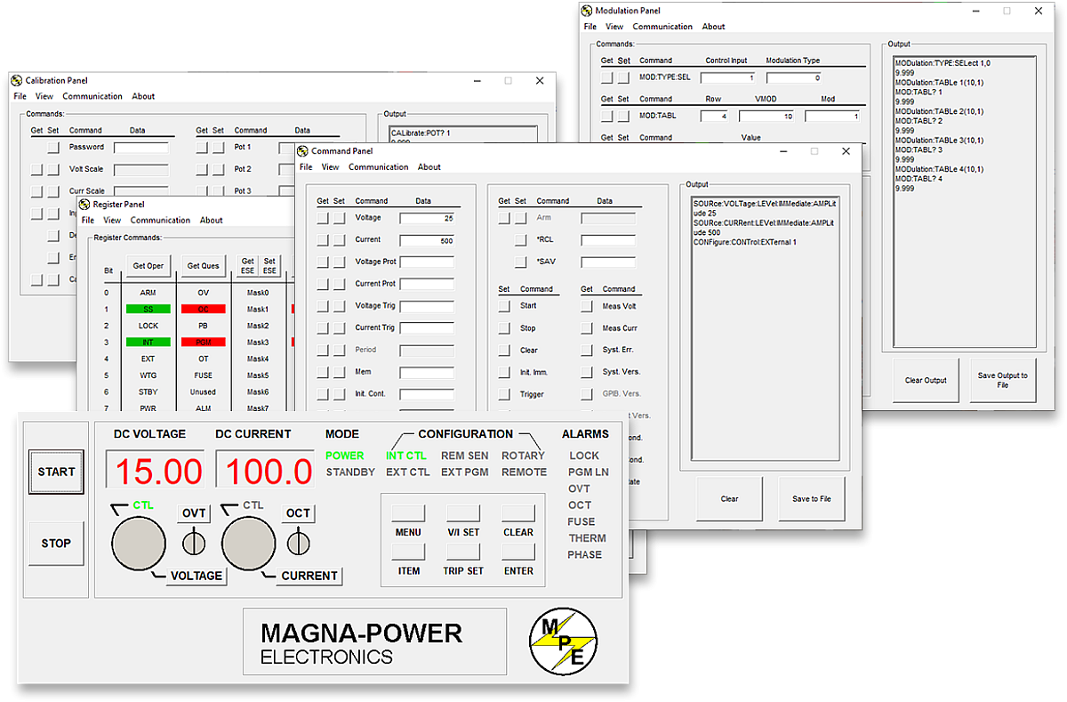
Jedes MagnaDC-Netzteil enthält einen IVI-Treiber und einen NI LabVIEW-Treiber mit einem vollständigen Satz von VIs sowie Beispielprogramme, mit denen Sie in wenigen Minuten mit der Hardware kommunizieren können. Für die direkte Steuerung im Bedienfeld-Stil von einem PC aus bietet die Remote Interface Software von Magna-Power einen umfassenden Einblick in das Netzteil – von Befehlen und Registern bis hin zu Kalibrierung und Firmware.
-
IVI- & NI LabVIEW-Treiber mit vollständigem VI-Satz enthalten.
-
Beispielprogramme für den schnellen Einstieg in Integration und Tests.
-
Remote Interface Software mit:
-
Virtuelles Bedienfeld für manuelle Steuerung
-
Befehlsfeld zum Erkunden und Senden von Befehlen
-
Registerfeld für Live-Statusüberwachung
-
Kalibrierungsfeld für interne digitale Potentiometer
-
Firmware-Feld für Vor-Ort-Upgrades
-
Modulationsfeld zur Emulation nichtlinearer Profile
-
-
Alle Kommunikationsschnittstellen werden software- und treiberübergreifend unterstützt – für ein einheitliches Programmiererlebnis.
State-of-the-art USA manufacturing with worldwide support

Made in the USA
Vertikal integrierte Fertigung für vollständige Qualitätskontrolle.
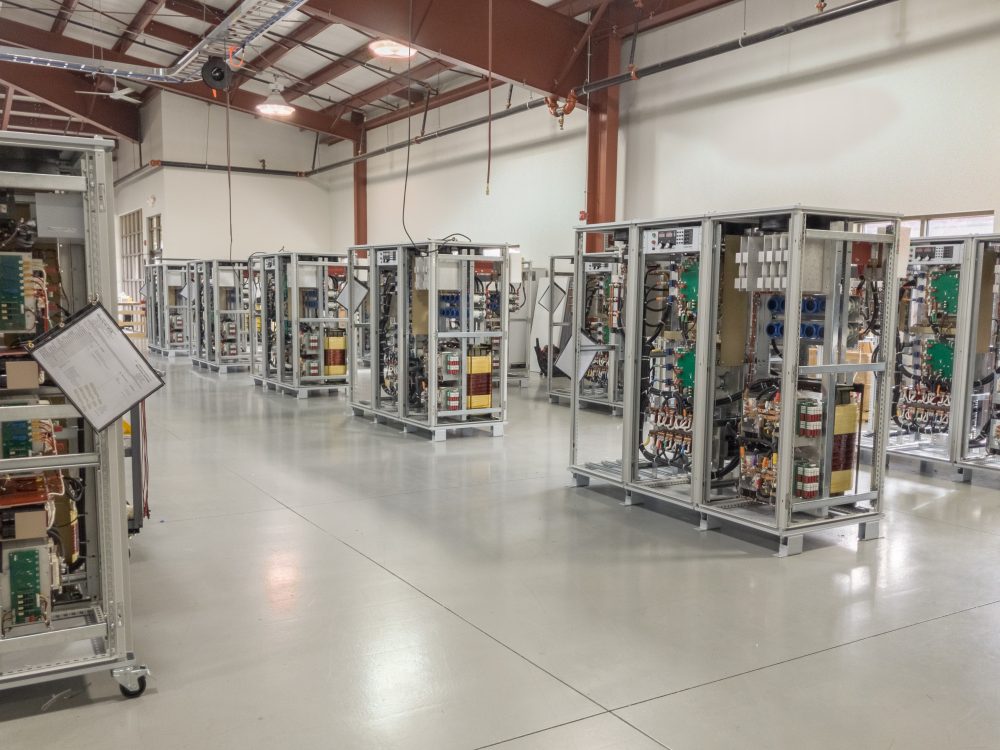
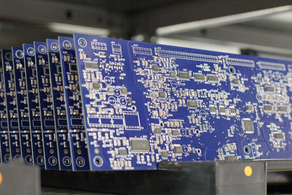
Magna-Power Produkte werden am 73.500 sq-ft großen Hauptsitz von Magna-Power in Flemington, New Jersey, entworfen, gebaut, getestet und gewartet. Metallbearbeitung, Magnetfertigung, PCB-Bestückung und Burn-in erfolgen vollständig im eigenen Haus – für maximale Kontrolle über Qualität, Kosten und Lieferzeiten.
- Made in USA: Entwicklung, Fertigung und Service unter einem Dach.
- Eigenfertigung: Metallbearbeitung, Magnetfertigung, SMT-PCBs und Oberflächenbehandlung.
- Bewährte Zuverlässigkeit: Jedes Gerät wird vollständig getestet, kalibriert und eingebrannt.
Weltweiter Service & OEM-Ersatzteilsupport
Fachwissen ab Werk, Reaktion vor Ort.
Magna-Power unterstützt seine Produkte mit werks- und autorisierten Servicezentren in Nordamerika, Europa, Großbritannien, dem asiatisch-pazifischen Raum, Ostasien und Südamerika – mit werkseitigen Verfahren und Originalteilen, um Geräte innerhalb und außerhalb der Garantie auf die ursprünglichen Spezifikationen zurückzusetzen.
- Globale Abdeckung: Hauptsitz in New Jersey sowie regionale autorisierte Servicezentren.
- Einheitliche Reparaturen: Werksdiagnosen, Arbeitsanweisungen und Systemdiagramme.
- Original-OEM-Teile: Geprüfte Ersatzbaugruppen für planbaren Service mit minimalen Ausfallzeiten.
Model Ordering Guide
For both ordering and production, MT Series models are uniquely defined by several key characteristics, as defined by the following diagram:

MT Series Models
There are 49 different models in the MT Series spanning power levels: 150 kW, 250 kW, 500 kW, 750 kW, 1000 kW+. To determine the appropriate model:
- Select the desired Max Voltage (Vdc) from the left-most column.
- Select the desired Max Current (Adc) from the same row that contains your desired Max Voltage.
- Construct your model number according to the model ordering guide.
| Max Voltage Vdc |
150 kW | 250 kW | 500 kW1 | 750 kW1 | 1000 kW1 | Ripple mVrms |
Efficiency |
|---|---|---|---|---|---|---|---|
| Max Current Adc | |||||||
| 32 | 4500 | — | — | — | — | 40 | 90% |
| 40 | 3750 | 6000 | 12000 | 18000 | 24000 | 40 | 91% |
| 50 | 3000 | 5000 | 10000 | 15000 | 20000 | 50 | 91% |
| 60 | 2500 | 4160 | 8320 | 12480 | 16640 | 60 | 91% |
| 80 | 1850 | 3000 | 6000 | 9000 | 12000 | 60 | 91% |
| 100 | 1500 | 2500 | 5000 | 7500 | 10000 | 60 | 91% |
| 125 | 1200 | 2000 | 4000 | 6000 | 8000 | 100 | 91% |
| 160 | 900 | 1500 | 3000 | 4500 | 6000 | 120 | 91% |
| 200 | 750 | 1250 | 2500 | 3750 | 5000 | 125 | 91% |
| 250 | 600 | 1000 | 2000 | 3000 | 4000 | 130 | 92% |
| 300 | 500 | 833 | 1666 | 2499 | 3332 | 160 | 92% |
| 375 | 400 | 660 | 1320 | 1980 | 2640 | 170 | 92% |
| 400 | 375 | 625 | 1250 | 1875 | 2500 | 180 | 92% |
| 500 | 300 | 500 | 1000 | 1500 | 2000 | 220 | 92% |
| 600 | 240 | 400 | 800 | 1200 | 1600 | 250 | 92% |
| 800 | 180 | 300 | 600 | 900 | 1200 | 300 | 92% |
| 1000 | 150 | 250 | 500 | 750 | 1000 | 400 | 92% |
| 1250 | 120 | 200 | 400 | 600 | 800 | 500 | 92% |
| 1600 | 90 | 150 | 300 | 450 | 600 | 600 | 92% |
| 2000 | 75 | 125 | 250 | 375 | 500 | 800 | 92% |
| 2500 | 60 | 100 | 200 | 300 | 400 | 900 | 92% |
| 3000 | 50 | 80 | 160 | 240 | 320 | 1000 | 92% |
| 4000 | 36 | 60 | 120 | 180 | 240 | 1100 | 92% |
| 5000 | 30 | 50 | 100 | 150 | 200 | 92% | |
| 6000 | 25 | 41.6 | 83.2 | 124.8 | 166.4 | 92% | |
| AC Input Voltage Vac |
Input Current Per Phase Aac | ||||||
| 380/415 Vac, 3Φ | 276 | 440 | 880 | 1320 | 1760 | ||
| 440/480 Vac, 3Φ | 238 | 380 | 760 | 1140 | 1520 | ||
1Power levels are achieved through master-slave parallel of 250 kW models. Contact sales for systems up to 3,000 kW.
Specifications are subject to change without notice. Unless otherwise noted, all specifications measured at the product's maximum ratings.
AC Input Specifications
415 Vac (operating range 373 to 456 Vac)
440 Vac (operating range 396 to 484 Vac)
480 Vac (operating range 432 to 528 Vac)
> 0.96 at maximum power, 250 kW models
DC Output Specifications
Current mode: ± 0.02% of full scale
Current mode: ± 0.04% of full scale
Model specific. Refer to chart of available models.
< 200 ms for a programmed output current change from 0 to 63%
< 10 ms for a programmed output current change from 0 to 63%
2 Hz with remote analog current programming
45 Hz with remote analog current programming
Programming Interface Specifications
LXI TCP/IP Ethernet RJ45 (Option +LXI)
IEEE-488 GPIB (Option +GPIB)
Referenced to Earth ground; isolated from power supply output
See User Manual for pin layout
Accuracy Specifications
External User I/O Specifications
Current output monitoring: 100 Ω
+10V reference: 1 Ω
Output: 0 to 5 Vdc, 5 mA drive capacity
Physical Specifications
67" H x 48" W x 31.5" D (170.2 x 121.9 x 80.0 cm)
1600 lbs (725.8 kg)
67" H x 48" W x 31.5" D (170.2 x 121.9 x 80.0 cm)
2100 lbs (952.5 kg)
67" H x 72" W x 31.5" D (170.2 x 182.9 x 80.0 cm)
3300 lbs (1496.9 kg)
Environmental Specifications
0.06%/°C of maximum output current
Regulatory Specifications
CISPR 22 / EN 55022 Class A
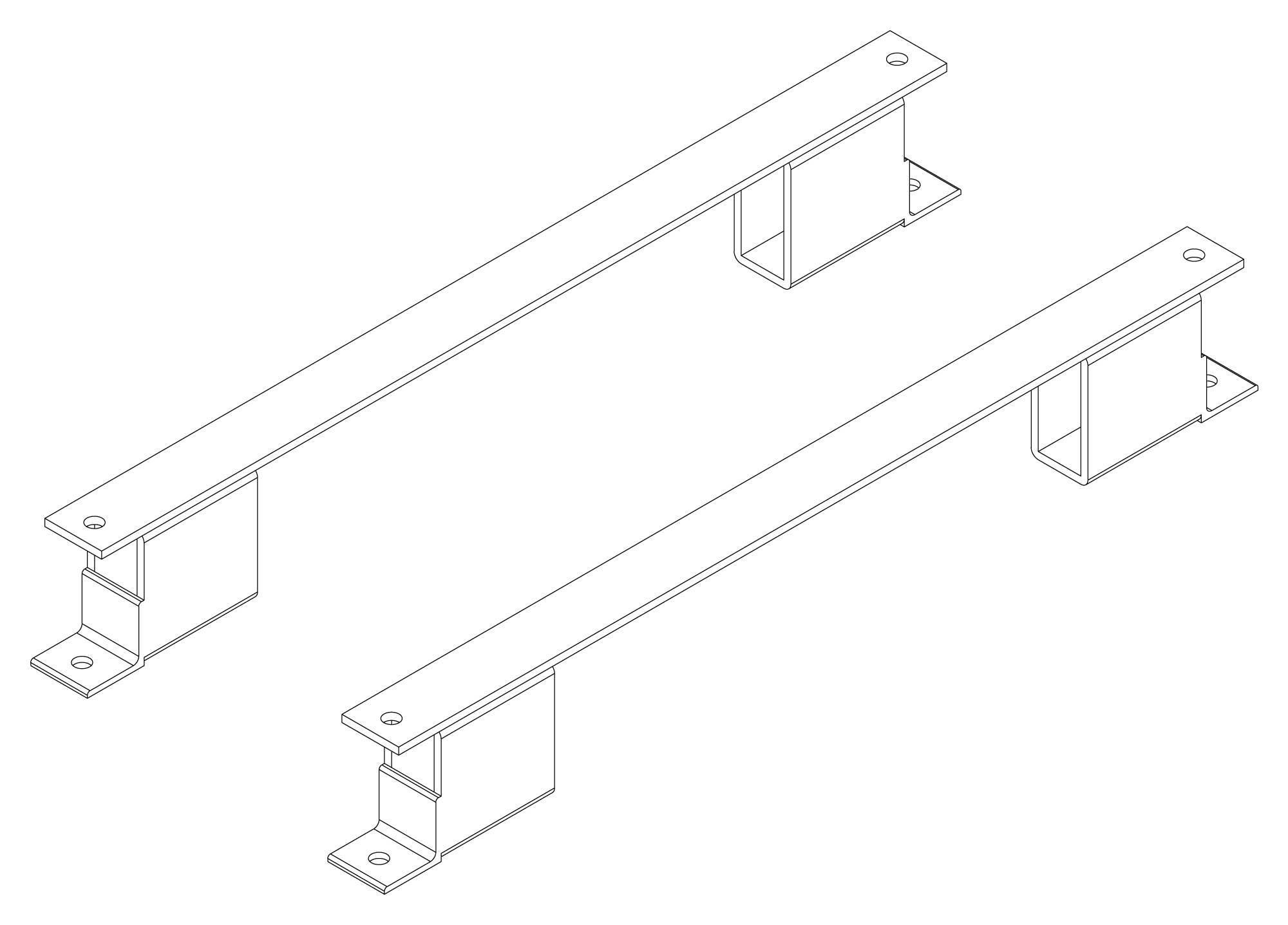
The following are vectorized diagrams for the MT Series. Refer to the Downloads section for downloadable drawings.


Integrated Options
Standard integrated options are available for Magna-Power products, allowing the product's performance and communication interfaces to be tailors to the specific application.
- Option
- +ISO
- Option
- +HS
- Option
- +GPIB
- Option
- +BD

Accessories
External accessories and integration services available for this product.