MT 시리즈
Programmable DC Power Supply
- Size
- 60U to 90U+
- Power
- 150 kW to 2000 kW+
- Manufactured
- USA
- Build-time
- 6-8 weeks
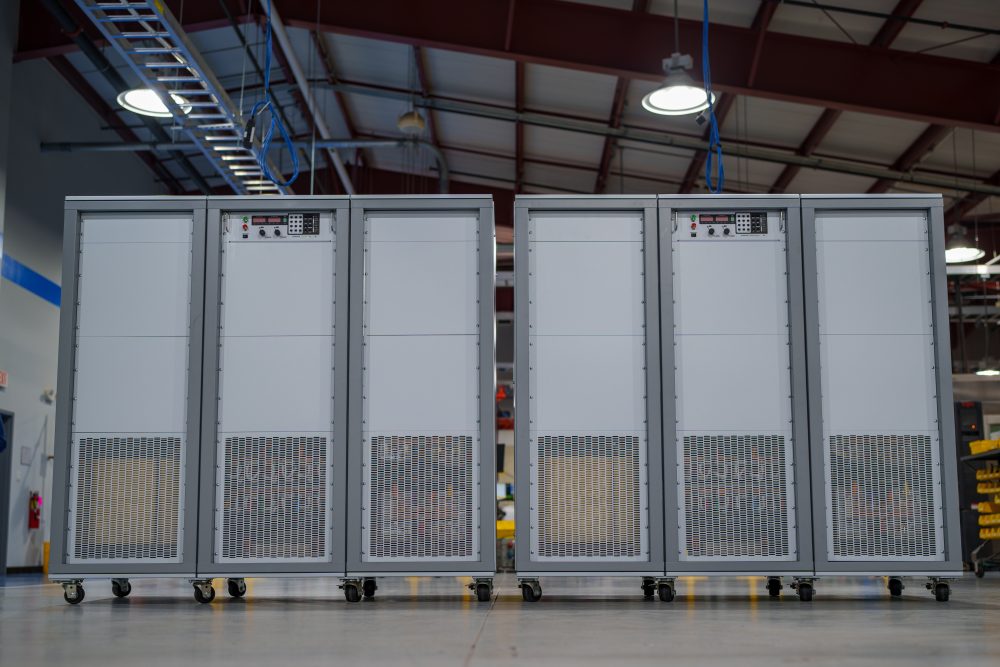
Magna-Power Electronics MT Series uses the same reliable current-fed power processing technology and controls as the rest of the MagnaDC programmable power supply product line, but with larger high-power modules: individual 150 kW and 250 kW power supplies. The high-frequency IGBT-based MT Series units are among the largest standard switched-mode power supplies on the market, minimizing the number of switching components when comparing to smaller module sizes. Scaling in the multi-megawatts is accomplished using the UID47 device, which provides master-slave control: one power supply takes command over the remaining units, for true system operation. As an added safety measure, all MT Series units include an input AC breaker rated for full power.
250 kW modules come standard with an embedded 12-pulse harmonic neutralizer, ensuring low total harmonic distortion (THD). Even higher quality AC waveforms are available with an external additional 500 kW 24-pulse or 1000 kW 48-pulse harmonic neutralizers, designed and manufactured exclusively by Magna-Power for its MT Series products.

Talk with an expert


High-power performance, harmonic control, and configurability for demanding systems
대규모 시스템을 위한 고성능 DC 전원
멀티 킬로와트에서 멀티 메가와트 시스템까지, 정밀하고 안정적인 출력을 제공합니다.
최대 6,000 Vdc(플로팅)의 광범위한 고전류 및 고전압 범위를 갖춘 MT Series 시스템은 빠른 과도 응답, 고정밀 프로그래밍 및 측정, 그리고 다양한 전력 레벨에서 낮은 출력 리플을 제공합니다. 정전압 또는 정전류 운전과 자동 크로스오버 기능을 통해 변동하는 부하에 신속하게 대응하고 목표값을 정밀하게 유지하며, 고전력 테스트 스탠드, 산업용 공정 전원, 그리고 성능이 중요한 멀티 메가와트 설비에 적합합니다.
통합 옵션으로 주문 맞춤 구성
풍부한 표준 기능, 필요 시 확장 가능.
MagnaDC 라인의 다른 제품들과 마찬가지로, MT Series 전원공급장치는 강력한 제어 기반을 갖추고 있습니다: RS232를 통한 SCPI, 절연된 후면 User I/O, LabVIEW 및 IVI 드라이버, Remote Interface Software가 포함되어 있습니다. 여기에 통합 옵션을 통해 각 시스템을 용도에 맞게 맞춤 구성할 수 있습니다—확장 직렬 스태킹을 위한 고절연 출력 (+ISO), 더 빠른 동적 응답을 위한 고속 슬루레이트 출력 (+HS), 추가 통신을 위한 LXI TCP/IP Ethernet (+LXI) 및 IEEE-488 GPIB (+GPIB), 그리고 고정 설치를 위한 통합 역류 방지 다이오드 (+BD) 및 페데스탈 베이스 (+PB) 등의 보호 및 기구 옵션이 제공됩니다.

블랭크 패널 옵션이 포함된 무단계 전면 패널 제어
필요한 곳에서는 직접 조작하고, 불필요한 곳에서는 깔끔하게 숨길 수 있습니다.
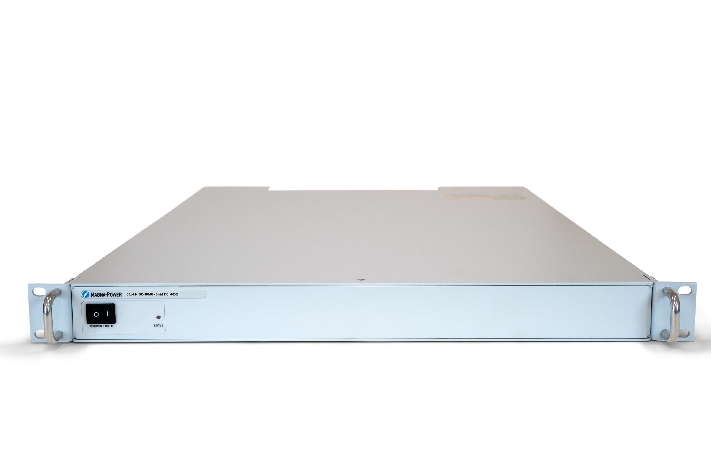
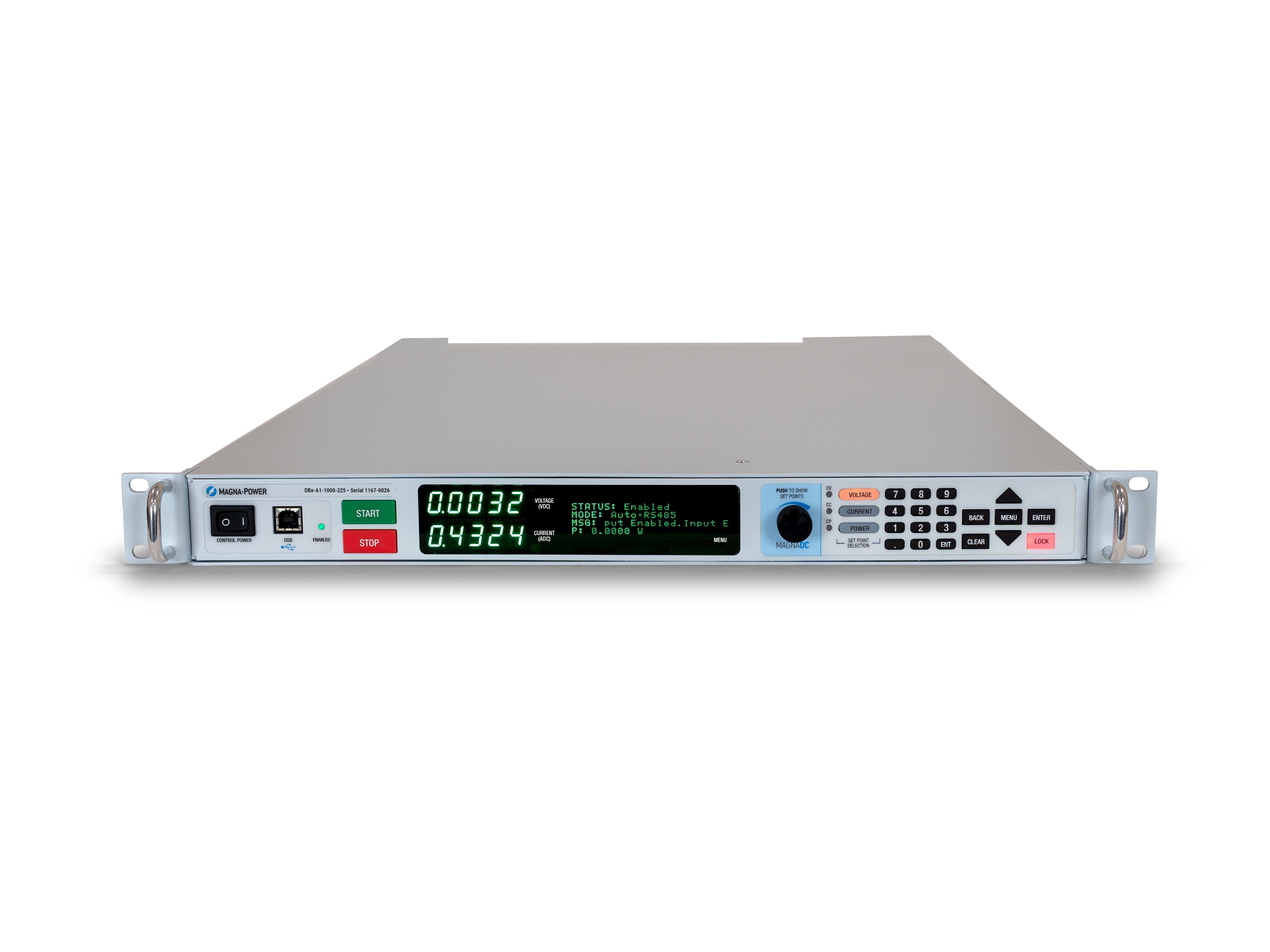
The standard SL front panel provides rotary and key-based control, bright digital metering, and clear status indicators, so operators can configure setpoints, start and stop the supply, and see system health at a glance. For OEMs and production tools, the optional blank (C-version) front panel removes local controls altogether while retaining full control via communication interfaces and rear 37-pin user I/O, keeping systems secure, clean, and operator-proof.
더 깨끗한 고출력 시스템을 위한 고조파 중화기
전원 품질 규정 준수를 용이하게 하기 위해 소스에서 THD를 저감합니다.
입력 전류 고조파는 3상 정류기의 고유한 부산물입니다. 표준 6펄스 프론트엔드는 기본파의 1, 5, 7, 11, 13… 배 주파수에서 고조파 전류를 생성하며, 5차 및 7차 성분만으로도 기본파의 약 20%와 14%에 달합니다. 이러한 전류는 직렬 커패시터/인덕터가 포함된 조명 안정기와 같은 민감한 부하를 여기시킬 수 있으며, IEEE 519와 같은 전력 품질 지침 준수를 더욱 어렵게 만듭니다. 고조파 문제를 최소화하는 가장 신뢰할 수 있는 방법은 소스에서 고조파 전류를 제거하는 것입니다.
고출력 시스템의 경우, Magna-Power는 입력 위상 수를 증가시키고 입력 전류 THD를 수동적으로 대폭 저감하는 특수 권선 고조파 중화기를 제조합니다. 표준 1.5–150 kW Magna-Power 전원 공급 장치는 6펄스 파형을 사용하며, 250 kW MT Series 및 500 kW ML Series 모델은 12펄스 고조파 중화기를, 1000 kW ML Series 모델은 24펄스 고조파 중화기를 내장하고 있으며, 이는 사용자에게 투명하게 작동합니다.

Rugged by design: safety + reliability, as you'd expect from Magna-Power.

신뢰성 높은 전류 공급형 전력 처리
견고한 설계: 가동 시간을 위한 자체 보호 토폴로지.
The SLx Series uses a high-frequency, current-fed architecture that adds a control stage beyond conventional voltage-fed designs. This topology inherently limits fault energy—avoiding fast-rising current spikes and magnetic core saturation so the supply self-protects and your load stays safe. Paired with state-of-the-art SiC power semiconductors, SLx delivers class-leading power density, efficiency, and reliability, including continuous full-power operation up to 50°C ambient.
- Current-fed architecture with an added control stage vs. voltage-fed.
- Inherent surge immunity—no current spikes or core saturation.
- Self-protecting behavior under fault conditions.
- SiC devices for high density and efficiency; full power to 50°C.
안전 기능 및 인터록
소프트 스타트, 프로그래밍 가능한 보호 기능, 그리고 진정한 안전을 위한 기계식 라인 차단 장치.
MagnaDC supplies start gently and watch continuously. A soft-start stage keeps inrush below steady-state draw, while built-in diagnostics monitor line, thermal, and control conditions. In standby or on a diagnostic fault, an embedded AC contactor mechanically disconnects the mains, assuring the unit only processes power when intended. Faults are shown on the front-panel status display, through 5V digital outputs, and are queryable via SCPI.
-
Programmable trips: Over voltage (OVT) and over current (OCT)/
-
Control integrity: Program-line over-voltage detection.
-
Thermal protection: Over temperature on internal heatsinks.
-
Interlock/E-stop fault monitoring as a standard diagnostic.
-
Field integration: 5V interlock input (with 5V reference) for a dry-contact, latching inhibit with control power maintained.
From lab scripts to factory PLCs, flexible programming & integration.
간편한 소프트웨어 통합
직관적인 명령어, 빠른 결과—모든 프로그래밍 언어와 호환됩니다.
MagnaDC 전원공급장치는 소켓 통신을 통해 전송되는 ASCII 기반 명령어인 네이티브 SCPI를 갖춘 명확한 텍스트 기반 API를 제공합니다. 40개 이상의 잘 문서화된 명령어가 시작/정지, 전압 및 전류 설정값, 고정밀 측정, 전체 구성을 지원하여 스크립트와 시스템을 개념 검증 단계에서 양산까지 신속하게 전환할 수 있습니다.
- 일관된 동작을 제공하는 SCPI 명령어 세트.
- 시작/정지 및 보호 기능: 출력 활성화, 트립 한계 설정, 상태 조회.
- 고정밀 측정: 전압, 전류, 전력 및 센스 피드백.
- 개발자 중심의 문서 및 예제 제공.
import serial
magnaPower = serial.Serial(port='COM4', baudrate=19200)
magnaPower.write('*IDN?\n'.encode())
print magna_power.readline()
magnaPower.write('VOLT 0\n'.encode())
magnaPower.write('CURR 0\n'.encode())
magnaPower.write('OUTP:START\n'.encode())
magnaPower.write('VOLT 270\n'.encode())
currSetPoints = [50, 100, 150, 250]
for currSetPoint in currSetPoints:
    print 'Setting Current to %s A' % currSetPoint
    magnaPower.write('CURR {0}\n'.format(currSetPoint).encode())
    magnaPower.write('MEAS:VOLT?\n'.encode())
    print magnaPower.readline()
    time.sleep(20)
magnaPower.write('OUTP:STOP\n'.encode())
magnaPower.close()
magna_power = serial('COM4', 'BaudRate', 19200);
fopen(magnaPower);
fprintf(magnaPower,'*IDN?');
idn = fscanf(magnaPower);
fprintf(magnaPower,'VOLT 0');
fprintf(magnaPower,'CURR 0');
fprintf(magnaPower,'OUTP:START');
fprintf(magnaPower,'VOLT 270');
for currSetPoint in [50, 100, 150, 250]
    display('Setting Current to '+currSetPoint+' A');
    fprintf(magnaPower, 'CURR '+currSetPoint);
    fprintf(magnaPower,'MEAS:VOLT?');
    display(fscanf(magnaPower));
    pause(20);
end
#include <stdio.h>
#include <stdint.h>
#include <string.h>
#include <windows.h>

int main()
{
    printf("Opening connection.\n");

    uint8_t recvBuffer[sizeof(uint8_t) * 256];
    memset(recvBuffer, 0, 256);

    // Choose the serial port name.
    // COM ports higher than COM9 need the \\.\ prefix, which is written as
    // "\\\\.\\" in C because we need to escape the backslashes.
    const char* device = "\\\\.\\COM4";

    // Choose the baud rate (bits per second).
    uint32_t baud_rate = 19200;

    HANDLE port = open_serial_port(device, baud_rate);
    if (port == INVALID_HANDLE_VALUE) { return 1; }

    char* scpiCmd = (char*)"*IDN?\n";
    size_t cmdLen = strlen(scpiCmd);
    int result = write_port(port, (uint8_t*)scpiCmd, cmdLen);
    if (result < 0)
        return -1;

    result = read_port(port, recvBuffer, 256);
    printf("Sent: %s\nReceived: %s\n", scpiCmd, recvBuffer);

    scpiCmd = (char*)"VOLT 0\n";
    cmdLen = strlen(scpiCmd);
    result = write_port(port, (uint8_t*)scpiCmd, cmdLen);
    if (result < 0)
        return -1;

    scpiCmd = (char*)"CURR 0\n";
    cmdLen = strlen(scpiCmd);
    result = write_port(port, (uint8_t*)scpiCmd, cmdLen);
    if (result < 0)
        return -1;

    scpiCmd = (char*)"OUTP:START\n";
    cmdLen = strlen(scpiCmd);
    result = write_port(port, (uint8_t*)scpiCmd, cmdLen);
    if (result < 0)
        return -1;

    scpiCmd = (char*)"VOLT 270\n";
    cmdLen = strlen(scpiCmd);
    result = write_port(port, (uint8_t*)scpiCmd, cmdLen);
    if (result < 0)
        return -1;

    char setPoints[4][5] = {"50", "100", "150", "200"};
    char setPointBuffer[40];
    scpiCmd = (char*)"MEAS:VOLT?\n";

    for (int i = 0; i < 4; i++)
    {
        sprintf(setPointBuffer, "CURR %s\n", setPoints[i]);
        printf("Setting current to %s A\n", setPoints[i]);
        cmdLen = strlen(setPointBuffer);
        result = write_port(port, (uint8_t*)setPointBuffer, cmdLen);
        if (result < 0)
            return -1;
        memset(recvBuffer, 0, 256);
        result = read_port(port, recvBuffer, 256);
        printf("Received: %s\n", recvBuffer);
        Sleep(20000);  // 20000ms = 20s
    }

    scpiCmd = (char*)"OUTP:STOP\n";
    cmdLen = strlen(scpiCmd);
    result = write_port(port, (uint8_t*)scpiCmd, cmdLen);
    if (result < 0)
        return -1;

    CloseHandle(port);

    printf("Connection closed.\n");
    return 0;
}
using System;
using System.IO.Ports;
using System.Threading;

namespace SerialCommunicationInCSharp
{
  public class Program
  {
    static bool _continue;
    static SerialPort serialPort;

    public static void Main(string[] args)
    {
      Thread readThread = new Thread(Read);

      Console.WriteLine("Opening connection.");

      // Create a new SerialPort object with default settings.
      serialPort = new SerialPort("COM4", 19200, Parity.None, 8, StopBits.One);

      // Set the read/write timeouts
      serialPort.ReadTimeout = 500;
      serialPort.WriteTimeout = 500;

      serialPort.Open();
      _continue = true;
      readThread.Start();

      Console.WriteLine("Sending: *IDN?");
      serialPort.WriteLine("*IDN?");

      serialPort.WriteLine("VOLT 0");
      serialPort.WriteLine("CURR 0");
      serialPort.WriteLine("OUTP:START");
      serialPort.WriteLine("VOLT 270");

      string[] currSetPoints = { "50", "100", "150", "250" };
ß
      for(int i = 0; i < currSetPoints.Length; i++)
      {
        serialPort.WriteLine(String.Format("'CURR {0}", currSetPoints[i]));
        serialPort.WriteLine("MEAS:VOLT?");
        Thread.Sleep(20000);
      }

      serialPort.WriteLine("OUTP:STOP");

      Console.WriteLine("Closing connection.");
      _continue = false;
      serialPort.Close();
      }

    public static void Read()
    {
      while (_continue)
      {
        try
        {
          string message = serialPort.ReadLine();
          Console.WriteLine("Received: " + message);
        }
        catch (TimeoutException) { }
      }
    }
  }
}

PLC 제어 또는 PHIL 시뮬레이션을 위한 외부 User I/O
I/O 모듈처럼 배선하세요—추가 절연이 필요 없습니다.
Via the included rear 37-pin User I/O connector, MagnaDC supplies can be fully driven and monitored by external signals or a PLC. Voltage, current, OVT, and OCT set points are programmed with 0–10 V analog inputs, while each diagnostic condition has its own +5V digital status pin. Built-in +2.5V, +5V, and +10V reference rails let you use dry contacts without adding external supplies. All I/O is isolated from the output and referenced to earth ground as standard.
-
0–10 V analog programming for V, I, OVT, and OCT.
-
Per-fault digital outputs: each diagnostic has its own +5V pin.
-
Isolated user I/O referenced to earth ground—no extra isolators.
-
With High Slew Rate Output (+HS), high-bandwidth response and fast rise times support HIL/PHIL simulation applications.
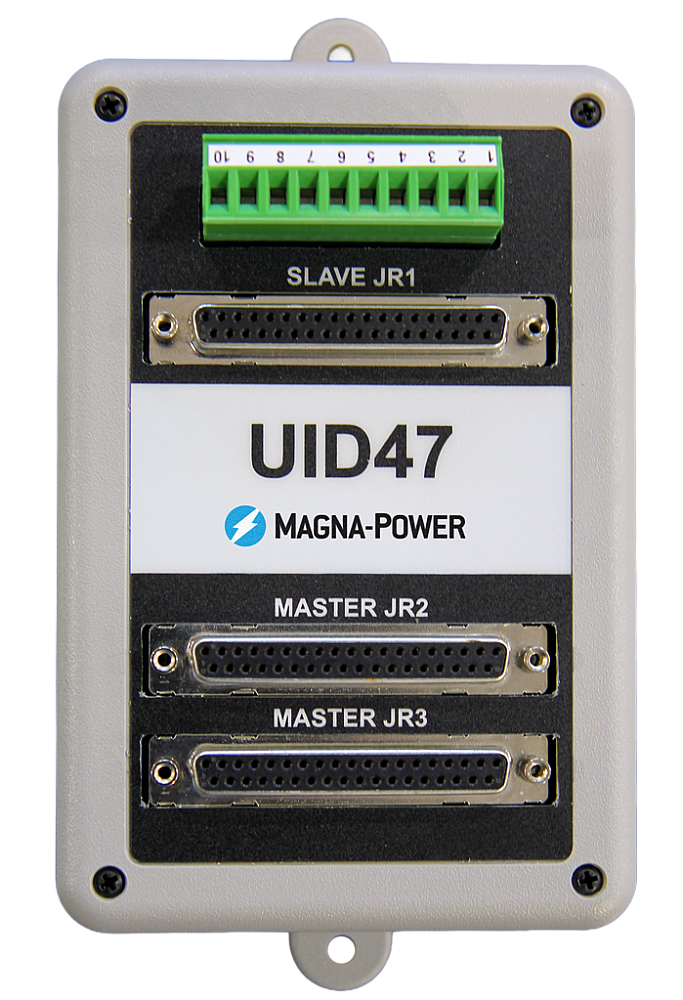
고성능 마스터-슬레이브 운전
성능 저하 없이 전압 또는 전류를 확장하십시오.
All MagnaDC supplies support master-slave operation, using gate-drive signals from the master when configured for parallel, so the whole stack behaves like a single supply—with one control loop and no noisy long analog references. The optional UID47 accessory simplifies wiring for series or parallel sets with near-equal sharing.
-
Single control loop parallel operation: Master gate-drive to slaves for consistent dynamics.
-
Plug & play with the UID47, enabling parallel or series stacks with current/voltage sharing.
-
Series up to the DC isolation rating without added hardware.
No additional ORing diodes required for parallel operation.
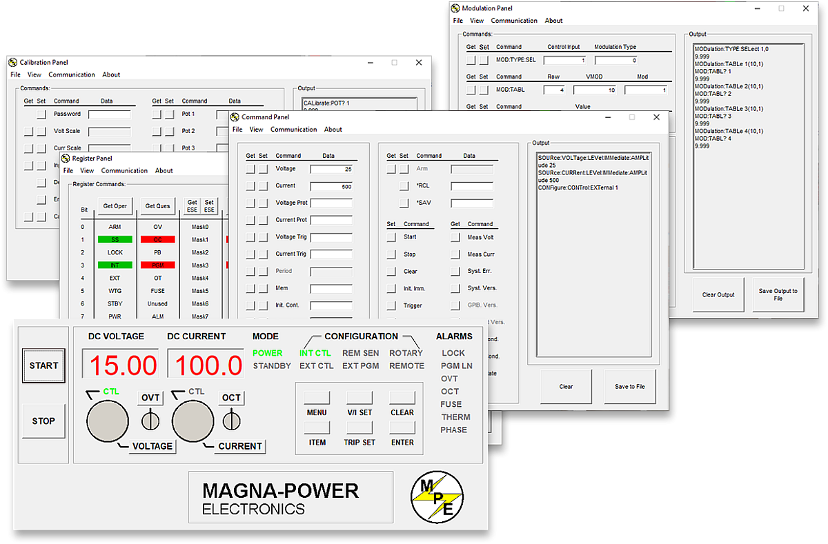
Magna-Power 소프트웨어, LabVIEW 및 IVI 드라이버
가상 전면 패널부터 완전 자동화까지—즉시 사용 가능합니다.
모든 MagnaDC 전원공급장치에는 IVI 드라이버와 NI LabVIEW 드라이버가 포함되어 있으며, 전체 VI 세트와 예제 프로그램이 함께 제공되어 몇 분 만에 하드웨어와 통신을 시작할 수 있습니다. PC에서 전면 패널 방식의 직접 제어를 위해, Magna-Power의 Remote Interface Software는 명령 및 레지스터부터 캘리브레이션 및 펌웨어까지 전원공급장치에 대한 풍부한 정보를 제공합니다.
-
전체 VI 세트가 포함된 IVI 및 NI LabVIEW 드라이버 제공.
-
통합 및 테스트를 신속하게 시작할 수 있는 예제 프로그램.
-
다음 기능을 갖춘 Remote Interface Software:
-
수동 제어를 위한 가상 전면 패널
-
명령 탐색 및 전송을 위한 명령 패널
-
실시간 상태 모니터링을 위한 레지스터 패널
-
내부 디지털 포텐셔미터용 캘리브레이션 패널
-
현장 업그레이드를 위한 펌웨어 패널
-
비선형 프로파일 에뮬레이션을 위한 모듈레이션 패널
-
-
일관된 프로그래밍 경험을 위해 모든 통신 인터페이스가 소프트웨어 및 드라이버 전반에서 지원됩니다.
State-of-the-art USA manufacturing with worldwide support

미국 제조
완벽한 품질 관리를 위한 수직 통합 제조.
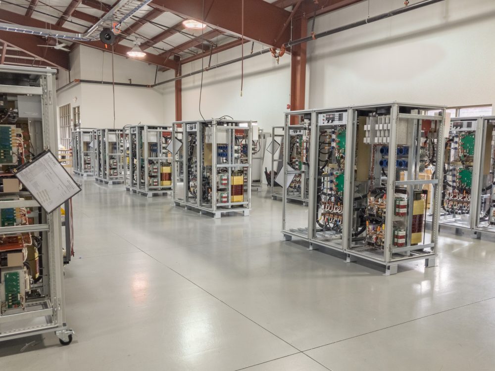
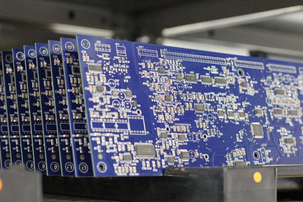
Magna-Power 제품은 뉴저지주 플레밍턴에 위치한 73,500 sq-ft 규모의 본사에서 설계, 제작, 테스트 및 서비스됩니다. 금속 가공, 자성 부품, PCB 조립, 번인 테스트까지 모두 자체적으로 수행하여 품질, 비용, 납기를 철저히 관리합니다.
- 미국 제조: 엔지니어링, 제조, 서비스를 한 지붕 아래에서.
- 자체 생산: 금속 가공, 자성 부품, SMT PCB, 표면 처리.
- 검증된 신뢰성: 모든 제품을 완벽하게 테스트, 교정, 번인 실시.
전 세계 서비스 및 OEM 부품 지원
공장 전문성, 현지 대응.
Magna-Power는 북미, 유럽, 영국, 아시아태평양, 동아시아, 남미 전역의 공장 및 공인 서비스 센터를 통해 자사 제품을 지원하며, 보증 기간 내외를 불문하고 공장 절차와 정품 부품을 사용하여 장비를 원래 사양으로 복원합니다.
- 글로벌 커버리지: 뉴저지 본사 및 지역 공인 서비스 센터.
- 일관된 수리: 공장 진단, 작업 지침서 및 시스템 다이어그램.
- 정품 OEM 부품: 검증된 교체 어셈블리로 예측 가능하고 다운타임이 적은 서비스 제공.
Model Ordering Guide
For both ordering and production, MT Series models are uniquely defined by several key characteristics, as defined by the following diagram:

MT Series Models
There are 49 different models in the MT Series spanning power levels: 150 kW, 250 kW, 500 kW, 750 kW, 1000 kW+. To determine the appropriate model:
- Select the desired Max Voltage (Vdc) from the left-most column.
- Select the desired Max Current (Adc) from the same row that contains your desired Max Voltage.
- Construct your model number according to the model ordering guide.
| Max Voltage Vdc |
150 kW | 250 kW | 500 kW1 | 750 kW1 | 1000 kW1 | Ripple mVrms |
Efficiency |
|---|---|---|---|---|---|---|---|
| Max Current Adc | |||||||
| 32 | 4500 | — | — | — | — | 40 | 90% |
| 40 | 3750 | 6000 | 12000 | 18000 | 24000 | 40 | 91% |
| 50 | 3000 | 5000 | 10000 | 15000 | 20000 | 50 | 91% |
| 60 | 2500 | 4160 | 8320 | 12480 | 16640 | 60 | 91% |
| 80 | 1850 | 3000 | 6000 | 9000 | 12000 | 60 | 91% |
| 100 | 1500 | 2500 | 5000 | 7500 | 10000 | 60 | 91% |
| 125 | 1200 | 2000 | 4000 | 6000 | 8000 | 100 | 91% |
| 160 | 900 | 1500 | 3000 | 4500 | 6000 | 120 | 91% |
| 200 | 750 | 1250 | 2500 | 3750 | 5000 | 125 | 91% |
| 250 | 600 | 1000 | 2000 | 3000 | 4000 | 130 | 92% |
| 300 | 500 | 833 | 1666 | 2499 | 3332 | 160 | 92% |
| 375 | 400 | 660 | 1320 | 1980 | 2640 | 170 | 92% |
| 400 | 375 | 625 | 1250 | 1875 | 2500 | 180 | 92% |
| 500 | 300 | 500 | 1000 | 1500 | 2000 | 220 | 92% |
| 600 | 240 | 400 | 800 | 1200 | 1600 | 250 | 92% |
| 800 | 180 | 300 | 600 | 900 | 1200 | 300 | 92% |
| 1000 | 150 | 250 | 500 | 750 | 1000 | 400 | 92% |
| 1250 | 120 | 200 | 400 | 600 | 800 | 500 | 92% |
| 1600 | 90 | 150 | 300 | 450 | 600 | 600 | 92% |
| 2000 | 75 | 125 | 250 | 375 | 500 | 800 | 92% |
| 2500 | 60 | 100 | 200 | 300 | 400 | 900 | 92% |
| 3000 | 50 | 80 | 160 | 240 | 320 | 1000 | 92% |
| 4000 | 36 | 60 | 120 | 180 | 240 | 1100 | 92% |
| 5000 | 30 | 50 | 100 | 150 | 200 | 92% | |
| 6000 | 25 | 41.6 | 83.2 | 124.8 | 166.4 | 92% | |
| AC Input Voltage Vac |
Input Current Per Phase Aac | ||||||
| 380/415 Vac, 3Φ | 276 | 440 | 880 | 1320 | 1760 | ||
| 440/480 Vac, 3Φ | 238 | 380 | 760 | 1140 | 1520 | ||
1Power levels are achieved through master-slave parallel of 250 kW models. Contact sales for systems up to 3,000 kW.
Specifications are subject to change without notice. Unless otherwise noted, all specifications measured at the product's maximum ratings.
AC Input Specifications
415 Vac (operating range 373 to 456 Vac)
440 Vac (operating range 396 to 484 Vac)
480 Vac (operating range 432 to 528 Vac)
> 0.96 at maximum power, 250 kW models
DC Output Specifications
Current mode: ± 0.02% of full scale
Current mode: ± 0.04% of full scale
Model specific. Refer to chart of available models.
< 200 ms for a programmed output current change from 0 to 63%
< 10 ms for a programmed output current change from 0 to 63%
2 Hz with remote analog current programming
45 Hz with remote analog current programming
Programming Interface Specifications
LXI TCP/IP Ethernet RJ45 (Option +LXI)
IEEE-488 GPIB (Option +GPIB)
Referenced to Earth ground; isolated from power supply output
See User Manual for pin layout
Accuracy Specifications
External User I/O Specifications
Current output monitoring: 100 Ω
+10V reference: 1 Ω
Output: 0 to 5 Vdc, 5 mA drive capacity
Physical Specifications
67" H x 48" W x 31.5" D (170.2 x 121.9 x 80.0 cm)
1600 lbs (725.8 kg)
67" H x 48" W x 31.5" D (170.2 x 121.9 x 80.0 cm)
2100 lbs (952.5 kg)
67" H x 72" W x 31.5" D (170.2 x 182.9 x 80.0 cm)
3300 lbs (1496.9 kg)
Environmental Specifications
0.06%/°C of maximum output current
Regulatory Specifications
CISPR 22 / EN 55022 Class A
The following are vectorized diagrams for the MT Series. Refer to the Downloads section for downloadable drawings.


Integrated Options
Standard integrated options are available for Magna-Power products, allowing the product's performance and communication interfaces to be tailors to the specific application.
- Option
- +ISO
- Option
- +HS
- Option
- +GPIB
- Option
- +BD

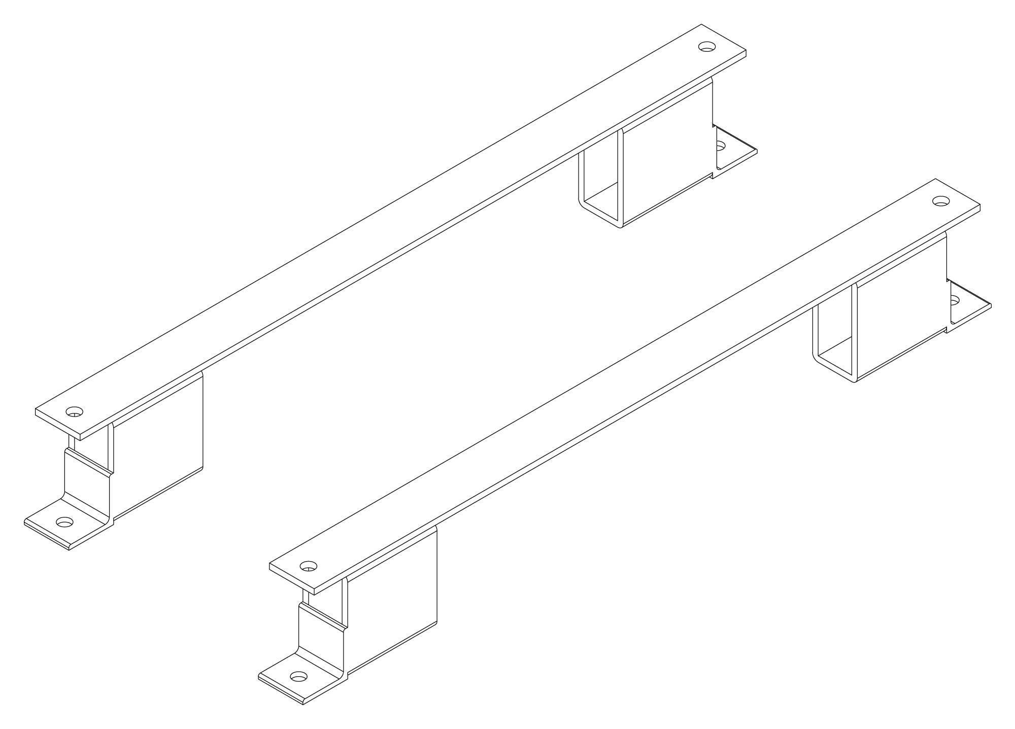
Accessories
External accessories and integration services available for this product.