Serie MT
Programmable DC Power Supply
- Size
- 60U to 90U+
- Power
- 150 kW to 2000 kW+
- Manufactured
- USA
- Build-time
- 6-8 weeks
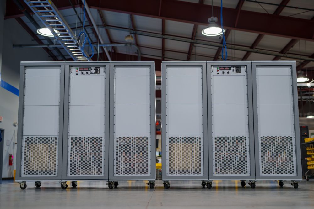
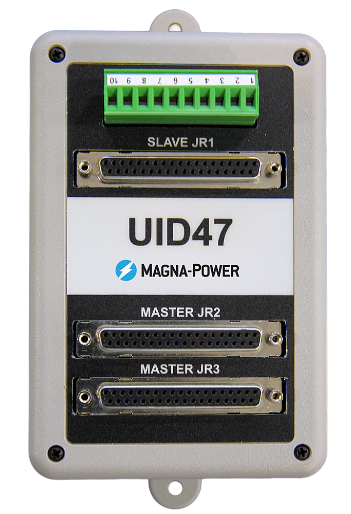
Magna-Power Electronics MT Series uses the same reliable current-fed power processing technology and controls as the rest of the MagnaDC programmable power supply product line, but with larger high-power modules: individual 150 kW and 250 kW power supplies. The high-frequency IGBT-based MT Series units are among the largest standard switched-mode power supplies on the market, minimizing the number of switching components when comparing to smaller module sizes. Scaling in the multi-megawatts is accomplished using the UID47 device, which provides master-slave control: one power supply takes command over the remaining units, for true system operation. As an added safety measure, all MT Series units include an input AC breaker rated for full power.
250 kW modules come standard with an embedded 12-pulse harmonic neutralizer, ensuring low total harmonic distortion (THD). Even higher quality AC waveforms are available with an external additional 500 kW 24-pulse or 1000 kW 48-pulse harmonic neutralizers, designed and manufactured exclusively by Magna-Power for its MT Series products.

Talk with an expert


High-power performance, harmonic control, and configurability for demanding systems
Alimentación DC de alto rendimiento a gran escala
Salida precisa y estable para sistemas de multi-kilovatios a multi-megavatios.
Con una amplia gama de alta corriente y alto voltaje de hasta 6,000 Vdc (flotante), los sistemas de la Serie MT ofrecen una respuesta transitoria rápida, programación y medición de alta precisión, y bajo rizado en la salida en una amplia gama de niveles de potencia. Con operación en voltaje constante o corriente constante y cruce automático, responden rápidamente a cargas cambiantes y mantienen sus valores objetivo con precisión, siendo ideales para bancos de pruebas de alta potencia, alimentación de procesos industriales e instalaciones de multi-megavatios donde el rendimiento es fundamental.
Configurado a pedido con opciones integradas
Funciones estándar completas, ampliadas cuando se necesitan.
Al igual que el resto de la línea MagnaDC, las fuentes MT Series comienzan con una sólida base de control: SCPI a través de RS232, E/S de usuario trasera aislada, controladores LabVIEW e IVI, y Remote Interface Software incluido. A partir de ahí, las opciones integradas le permiten adaptar cada sistema a su función—Salida de alto aislamiento (+ISO) para apilamiento en serie extendido, Salida de alta velocidad de respuesta (+HS) para dinámicas más rápidas, LXI TCP/IP Ethernet (+LXI) y IEEE-488 GPIB (+GPIB) para comunicaciones adicionales, además de opciones de protección y mecánicas como un diodo de bloqueo integrado (+BD) y base tipo pedestal (+PB) para instalaciones fijas.
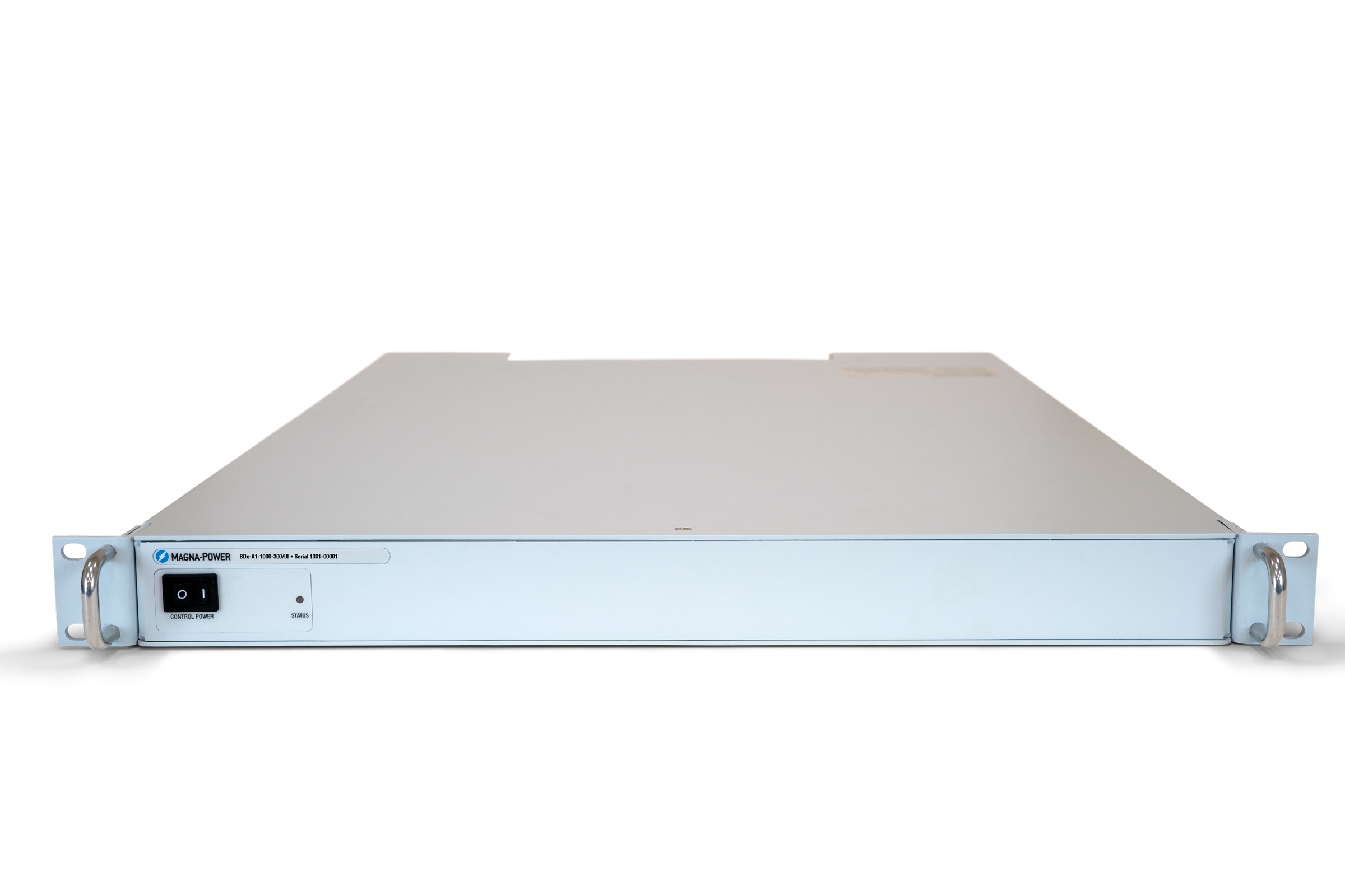
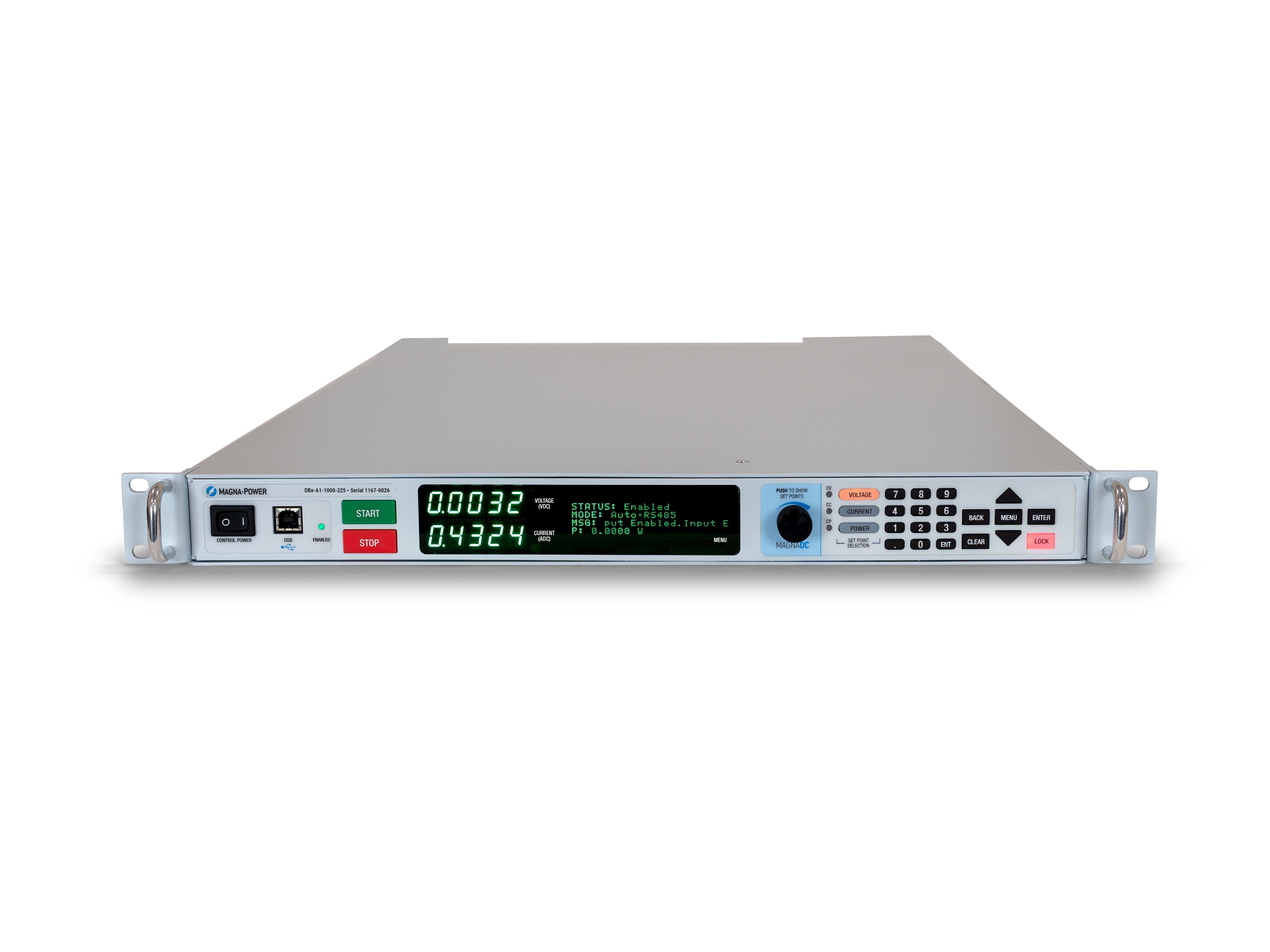
Control continuo del panel frontal con opción de panel en blanco
Acceso directo donde lo necesita, oculto donde no.
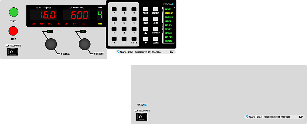
The standard SL front panel provides rotary and key-based control, bright digital metering, and clear status indicators, so operators can configure setpoints, start and stop the supply, and see system health at a glance. For OEMs and production tools, the optional blank (C-version) front panel removes local controls altogether while retaining full control via communication interfaces and rear 37-pin user I/O, keeping systems secure, clean, and operator-proof.
Harmonic Neutralizers para sistemas de alta potencia más limpios
Reduzca el THD en la fuente para un cumplimiento más sencillo de la calidad de energía.
Los armónicos de corriente de entrada son un subproducto inherente de los rectificadores trifásicos: un front end estándar de 6 pulsos produce corrientes armónicas a 1, 5, 7, 11, 13… veces la fundamental, con los componentes 5º y 7º solos aproximadamente al 20% y 14% de la fundamental. Estas corrientes pueden excitar cargas sensibles—como balastos de iluminación con capacitores/inductores en serie—y dificultar el cumplimiento de directrices de calidad de energía como IEEE 519. La forma más confiable de minimizar los problemas de armónicos es eliminar la corriente armónica en la fuente.
Para sistemas de alta potencia, Magna-Power fabrica Harmonic Neutralizers de bobinado especial que multiplican el número de fases de entrada y reducen drásticamente el THD de corriente de entrada, de forma pasiva. Las fuentes estándar de Magna-Power de 1.5–150 kW generan una forma de onda de 6 pulsos, mientras que los modelos de 250 kW de la MT Series y de 500 kW de la ML Series incorporan un Harmonic Neutralizer de 12 pulsos, y los modelos de 1000 kW de la ML Series incorporan un Harmonic Neutralizer de 24 pulsos—de forma transparente para el usuario.

Rugged by design: safety + reliability, as you'd expect from Magna-Power.

Procesamiento de potencia confiable alimentado por corriente
Robusto por diseño: topología autoprotegida para máximo tiempo de actividad.
The SLx Series uses a high-frequency, current-fed architecture that adds a control stage beyond conventional voltage-fed designs. This topology inherently limits fault energy—avoiding fast-rising current spikes and magnetic core saturation so the supply self-protects and your load stays safe. Paired with state-of-the-art SiC power semiconductors, SLx delivers class-leading power density, efficiency, and reliability, including continuous full-power operation up to 50°C ambient.
- Current-fed architecture with an added control stage vs. voltage-fed.
- Inherent surge immunity—no current spikes or core saturation.
- Self-protecting behavior under fault conditions.
- SiC devices for high density and efficiency; full power to 50°C.
Características de seguridad e interbloqueo
Arranque suave, protección programable y desconexión mecánica de línea para una verdadera seguridad.
MagnaDC supplies start gently and watch continuously. A soft-start stage keeps inrush below steady-state draw, while built-in diagnostics monitor line, thermal, and control conditions. In standby or on a diagnostic fault, an embedded AC contactor mechanically disconnects the mains, assuring the unit only processes power when intended. Faults are shown on the front-panel status display, through 5V digital outputs, and are queryable via SCPI.
-
Programmable trips: Over voltage (OVT) and over current (OCT)/
-
Control integrity: Program-line over-voltage detection.
-
Thermal protection: Over temperature on internal heatsinks.
-
Interlock/E-stop fault monitoring as a standard diagnostic.
-
Field integration: 5V interlock input (with 5V reference) for a dry-contact, latching inhibit with control power maintained.
From lab scripts to factory PLCs, flexible programming & integration.
Integración de software simplificada
Comandos legibles, resultados rápidos—funciona con cualquier lenguaje.
Las fuentes de alimentación MagnaDC ofrecen una API clara basada en texto con SCPI nativo, un lenguaje de comandos basado en ASCII enviado a través de comunicaciones por socket. Más de 40 comandos bien documentados cubren inicio/parada, puntos de ajuste de voltaje, corriente, mediciones de alta precisión y configuración completa—para que sus scripts y sistemas pasen del concepto a la producción rápidamente.
- Conjuntos de comandos SCPI con comportamiento consistente.
- Inicio/parada y protecciones: habilitar salida, establecer límites de disparo, consultar estado.
- Lecturas de alta precisión: voltaje, corriente, potencia y retroalimentación de sensor.
- Documentación y ejemplos orientados al desarrollador.
import serial
magnaPower = serial.Serial(port='COM4', baudrate=19200)
magnaPower.write('*IDN?\n'.encode())
print magna_power.readline()
magnaPower.write('VOLT 0\n'.encode())
magnaPower.write('CURR 0\n'.encode())
magnaPower.write('OUTP:START\n'.encode())
magnaPower.write('VOLT 270\n'.encode())
currSetPoints = [50, 100, 150, 250]
for currSetPoint in currSetPoints:
    print 'Setting Current to %s A' % currSetPoint
    magnaPower.write('CURR {0}\n'.format(currSetPoint).encode())
    magnaPower.write('MEAS:VOLT?\n'.encode())
    print magnaPower.readline()
    time.sleep(20)
magnaPower.write('OUTP:STOP\n'.encode())
magnaPower.close()
magna_power = serial('COM4', 'BaudRate', 19200);
fopen(magnaPower);
fprintf(magnaPower,'*IDN?');
idn = fscanf(magnaPower);
fprintf(magnaPower,'VOLT 0');
fprintf(magnaPower,'CURR 0');
fprintf(magnaPower,'OUTP:START');
fprintf(magnaPower,'VOLT 270');
for currSetPoint in [50, 100, 150, 250]
    display('Setting Current to '+currSetPoint+' A');
    fprintf(magnaPower, 'CURR '+currSetPoint);
    fprintf(magnaPower,'MEAS:VOLT?');
    display(fscanf(magnaPower));
    pause(20);
end
#include <stdio.h>
#include <stdint.h>
#include <string.h>
#include <windows.h>

int main()
{
    printf("Opening connection.\n");

    uint8_t recvBuffer[sizeof(uint8_t) * 256];
    memset(recvBuffer, 0, 256);

    // Choose the serial port name.
    // COM ports higher than COM9 need the \\.\ prefix, which is written as
    // "\\\\.\\" in C because we need to escape the backslashes.
    const char* device = "\\\\.\\COM4";

    // Choose the baud rate (bits per second).
    uint32_t baud_rate = 19200;

    HANDLE port = open_serial_port(device, baud_rate);
    if (port == INVALID_HANDLE_VALUE) { return 1; }

    char* scpiCmd = (char*)"*IDN?\n";
    size_t cmdLen = strlen(scpiCmd);
    int result = write_port(port, (uint8_t*)scpiCmd, cmdLen);
    if (result < 0)
        return -1;

    result = read_port(port, recvBuffer, 256);
    printf("Sent: %s\nReceived: %s\n", scpiCmd, recvBuffer);

    scpiCmd = (char*)"VOLT 0\n";
    cmdLen = strlen(scpiCmd);
    result = write_port(port, (uint8_t*)scpiCmd, cmdLen);
    if (result < 0)
        return -1;

    scpiCmd = (char*)"CURR 0\n";
    cmdLen = strlen(scpiCmd);
    result = write_port(port, (uint8_t*)scpiCmd, cmdLen);
    if (result < 0)
        return -1;

    scpiCmd = (char*)"OUTP:START\n";
    cmdLen = strlen(scpiCmd);
    result = write_port(port, (uint8_t*)scpiCmd, cmdLen);
    if (result < 0)
        return -1;

    scpiCmd = (char*)"VOLT 270\n";
    cmdLen = strlen(scpiCmd);
    result = write_port(port, (uint8_t*)scpiCmd, cmdLen);
    if (result < 0)
        return -1;

    char setPoints[4][5] = {"50", "100", "150", "200"};
    char setPointBuffer[40];
    scpiCmd = (char*)"MEAS:VOLT?\n";

    for (int i = 0; i < 4; i++)
    {
        sprintf(setPointBuffer, "CURR %s\n", setPoints[i]);
        printf("Setting current to %s A\n", setPoints[i]);
        cmdLen = strlen(setPointBuffer);
        result = write_port(port, (uint8_t*)setPointBuffer, cmdLen);
        if (result < 0)
            return -1;
        memset(recvBuffer, 0, 256);
        result = read_port(port, recvBuffer, 256);
        printf("Received: %s\n", recvBuffer);
        Sleep(20000);  // 20000ms = 20s
    }

    scpiCmd = (char*)"OUTP:STOP\n";
    cmdLen = strlen(scpiCmd);
    result = write_port(port, (uint8_t*)scpiCmd, cmdLen);
    if (result < 0)
        return -1;

    CloseHandle(port);

    printf("Connection closed.\n");
    return 0;
}
using System;
using System.IO.Ports;
using System.Threading;

namespace SerialCommunicationInCSharp
{
  public class Program
  {
    static bool _continue;
    static SerialPort serialPort;

    public static void Main(string[] args)
    {
      Thread readThread = new Thread(Read);

      Console.WriteLine("Opening connection.");

      // Create a new SerialPort object with default settings.
      serialPort = new SerialPort("COM4", 19200, Parity.None, 8, StopBits.One);

      // Set the read/write timeouts
      serialPort.ReadTimeout = 500;
      serialPort.WriteTimeout = 500;

      serialPort.Open();
      _continue = true;
      readThread.Start();

      Console.WriteLine("Sending: *IDN?");
      serialPort.WriteLine("*IDN?");

      serialPort.WriteLine("VOLT 0");
      serialPort.WriteLine("CURR 0");
      serialPort.WriteLine("OUTP:START");
      serialPort.WriteLine("VOLT 270");

      string[] currSetPoints = { "50", "100", "150", "250" };
ß
      for(int i = 0; i < currSetPoints.Length; i++)
      {
        serialPort.WriteLine(String.Format("'CURR {0}", currSetPoints[i]));
        serialPort.WriteLine("MEAS:VOLT?");
        Thread.Sleep(20000);
      }

      serialPort.WriteLine("OUTP:STOP");

      Console.WriteLine("Closing connection.");
      _continue = false;
      serialPort.Close();
      }

    public static void Read()
    {
      while (_continue)
      {
        try
        {
          string message = serialPort.ReadLine();
          Console.WriteLine("Received: " + message);
        }
        catch (TimeoutException) { }
      }
    }
  }
}

E/S de usuario externa para control PLC o simulación PHIL
Conéctelo como un módulo de E/S, sin necesidad de aislamiento adicional.
Via the included rear 37-pin User I/O connector, MagnaDC supplies can be fully driven and monitored by external signals or a PLC. Voltage, current, OVT, and OCT set points are programmed with 0–10 V analog inputs, while each diagnostic condition has its own +5V digital status pin. Built-in +2.5V, +5V, and +10V reference rails let you use dry contacts without adding external supplies. All I/O is isolated from the output and referenced to earth ground as standard.
-
0–10 V analog programming for V, I, OVT, and OCT.
-
Per-fault digital outputs: each diagnostic has its own +5V pin.
-
Isolated user I/O referenced to earth ground—no extra isolators.
-
With High Slew Rate Output (+HS), high-bandwidth response and fast rise times support HIL/PHIL simulation applications.
Operación maestro-esclavo de alto rendimiento
Escale voltaje o corriente sin sacrificar rendimiento.
All MagnaDC supplies support master-slave operation, using gate-drive signals from the master when configured for parallel, so the whole stack behaves like a single supply—with one control loop and no noisy long analog references. The optional UID47 accessory simplifies wiring for series or parallel sets with near-equal sharing.
-
Single control loop parallel operation: Master gate-drive to slaves for consistent dynamics.
-
Plug & play with the UID47, enabling parallel or series stacks with current/voltage sharing.
-
Series up to the DC isolation rating without added hardware.
No additional ORing diodes required for parallel operation.
Software, controladores LabVIEW e IVI de Magna-Power
Del panel frontal virtual a la automatización completa, listo para usar.
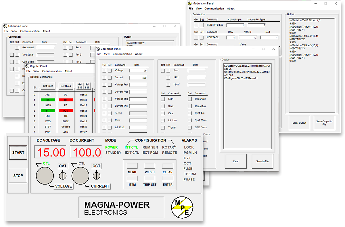
Cada fuente MagnaDC incluye un controlador IVI y un controlador NI LabVIEW con un conjunto completo de VIs, además de programas de ejemplo para que pueda comunicarse con el hardware en minutos. Para el control directo estilo panel frontal desde una PC, el software de interfaz remota de Magna-Power ofrece una vista completa de la fuente, desde comandos y registros hasta calibración y firmware.
-
Controladores IVI y NI LabVIEW incluidos con conjunto completo de VIs.
-
Programas de ejemplo para acelerar la integración y las pruebas.
-
Software de interfaz remota con:
-
Panel frontal virtual para control manual
-
Panel de comandos para explorar y enviar comandos
-
Panel de registros para monitoreo de estado en tiempo real
-
Panel de calibración para potenciómetros digitales internos
-
Panel de firmware para actualizaciones en sitio
-
Panel de modulación para emular perfiles no lineales
-
-
Todas las interfaces de comunicación compatibles con el software y los controladores para una experiencia de programación consistente.
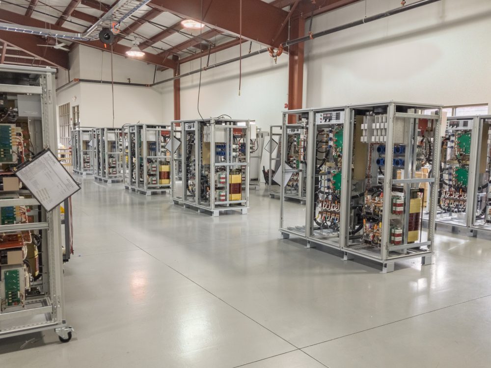
State-of-the-art USA manufacturing with worldwide support

Made in the USA
Fabricación verticalmente integrada para un control de calidad total.
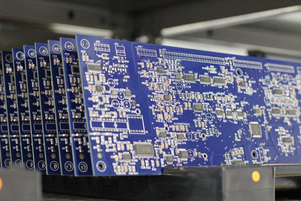
Los productos de Magna-Power se diseñan, fabrican, prueban y reciben servicio en la sede central de Magna-Power de 73,500 sq-ft en Flemington, New Jersey, donde el trabajo en metal, los magnéticos, el ensamblaje de PCB y el rodaje se realizan internamente para un control riguroso de la calidad, los costos y los tiempos de entrega.
- Fabricado en EE. UU.: Ingeniería, manufactura y servicio bajo un mismo techo.
- Producción interna: Trabajo en metal, magnéticos, PCBs SMT y acabados.
- Fiabilidad comprobada: Cada unidad completamente probada, calibrada y sometida a rodaje.
Servicio mundial y soporte de piezas OEM
Experiencia de fábrica, respuesta local.
Magna-Power respalda sus productos con centros de servicio de fábrica y autorizados en América del Norte, Europa, el Reino Unido, Asia-Pacífico, Asia Oriental y América del Sur, utilizando procedimientos de fábrica y piezas originales para restaurar las unidades a sus especificaciones originales, dentro o fuera de garantía.
- Cobertura global: sede central en Nueva Jersey más centros de servicio autorizados regionales.
- Reparaciones consistentes: diagnósticos de fábrica, instrucciones de trabajo y diagramas del sistema.
- Piezas OEM originales: ensamblajes de repuesto probados para un servicio predecible y con mínimo tiempo de inactividad.
Model Ordering Guide
For both ordering and production, MT Series models are uniquely defined by several key characteristics, as defined by the following diagram:

MT Series Models
There are 49 different models in the MT Series spanning power levels: 150 kW, 250 kW, 500 kW, 750 kW, 1000 kW+. To determine the appropriate model:
- Select the desired Max Voltage (Vdc) from the left-most column.
- Select the desired Max Current (Adc) from the same row that contains your desired Max Voltage.
- Construct your model number according to the model ordering guide.
| Max Voltage Vdc |
150 kW | 250 kW | 500 kW1 | 750 kW1 | 1000 kW1 | Ripple mVrms |
Efficiency |
|---|---|---|---|---|---|---|---|
| Max Current Adc | |||||||
| 32 | 4500 | — | — | — | — | 40 | 90% |
| 40 | 3750 | 6000 | 12000 | 18000 | 24000 | 40 | 91% |
| 50 | 3000 | 5000 | 10000 | 15000 | 20000 | 50 | 91% |
| 60 | 2500 | 4160 | 8320 | 12480 | 16640 | 60 | 91% |
| 80 | 1850 | 3000 | 6000 | 9000 | 12000 | 60 | 91% |
| 100 | 1500 | 2500 | 5000 | 7500 | 10000 | 60 | 91% |
| 125 | 1200 | 2000 | 4000 | 6000 | 8000 | 100 | 91% |
| 160 | 900 | 1500 | 3000 | 4500 | 6000 | 120 | 91% |
| 200 | 750 | 1250 | 2500 | 3750 | 5000 | 125 | 91% |
| 250 | 600 | 1000 | 2000 | 3000 | 4000 | 130 | 92% |
| 300 | 500 | 833 | 1666 | 2499 | 3332 | 160 | 92% |
| 375 | 400 | 660 | 1320 | 1980 | 2640 | 170 | 92% |
| 400 | 375 | 625 | 1250 | 1875 | 2500 | 180 | 92% |
| 500 | 300 | 500 | 1000 | 1500 | 2000 | 220 | 92% |
| 600 | 240 | 400 | 800 | 1200 | 1600 | 250 | 92% |
| 800 | 180 | 300 | 600 | 900 | 1200 | 300 | 92% |
| 1000 | 150 | 250 | 500 | 750 | 1000 | 400 | 92% |
| 1250 | 120 | 200 | 400 | 600 | 800 | 500 | 92% |
| 1600 | 90 | 150 | 300 | 450 | 600 | 600 | 92% |
| 2000 | 75 | 125 | 250 | 375 | 500 | 800 | 92% |
| 2500 | 60 | 100 | 200 | 300 | 400 | 900 | 92% |
| 3000 | 50 | 80 | 160 | 240 | 320 | 1000 | 92% |
| 4000 | 36 | 60 | 120 | 180 | 240 | 1100 | 92% |
| 5000 | 30 | 50 | 100 | 150 | 200 | 92% | |
| 6000 | 25 | 41.6 | 83.2 | 124.8 | 166.4 | 92% | |
| AC Input Voltage Vac |
Input Current Per Phase Aac | ||||||
| 380/415 Vac, 3Φ | 276 | 440 | 880 | 1320 | 1760 | ||
| 440/480 Vac, 3Φ | 238 | 380 | 760 | 1140 | 1520 | ||
1Power levels are achieved through master-slave parallel of 250 kW models. Contact sales for systems up to 3,000 kW.
Specifications are subject to change without notice. Unless otherwise noted, all specifications measured at the product's maximum ratings.
AC Input Specifications
415 Vac (operating range 373 to 456 Vac)
440 Vac (operating range 396 to 484 Vac)
480 Vac (operating range 432 to 528 Vac)
> 0.96 at maximum power, 250 kW models
DC Output Specifications
Current mode: ± 0.02% of full scale
Current mode: ± 0.04% of full scale
Model specific. Refer to chart of available models.
< 200 ms for a programmed output current change from 0 to 63%
< 10 ms for a programmed output current change from 0 to 63%
2 Hz with remote analog current programming
45 Hz with remote analog current programming
Programming Interface Specifications
LXI TCP/IP Ethernet RJ45 (Option +LXI)
IEEE-488 GPIB (Option +GPIB)
Referenced to Earth ground; isolated from power supply output
See User Manual for pin layout
Accuracy Specifications
External User I/O Specifications
Current output monitoring: 100 Ω
+10V reference: 1 Ω
Output: 0 to 5 Vdc, 5 mA drive capacity
Physical Specifications
67" H x 48" W x 31.5" D (170.2 x 121.9 x 80.0 cm)
1600 lbs (725.8 kg)
67" H x 48" W x 31.5" D (170.2 x 121.9 x 80.0 cm)
2100 lbs (952.5 kg)
67" H x 72" W x 31.5" D (170.2 x 182.9 x 80.0 cm)
3300 lbs (1496.9 kg)
Environmental Specifications
0.06%/°C of maximum output current
Regulatory Specifications
CISPR 22 / EN 55022 Class A
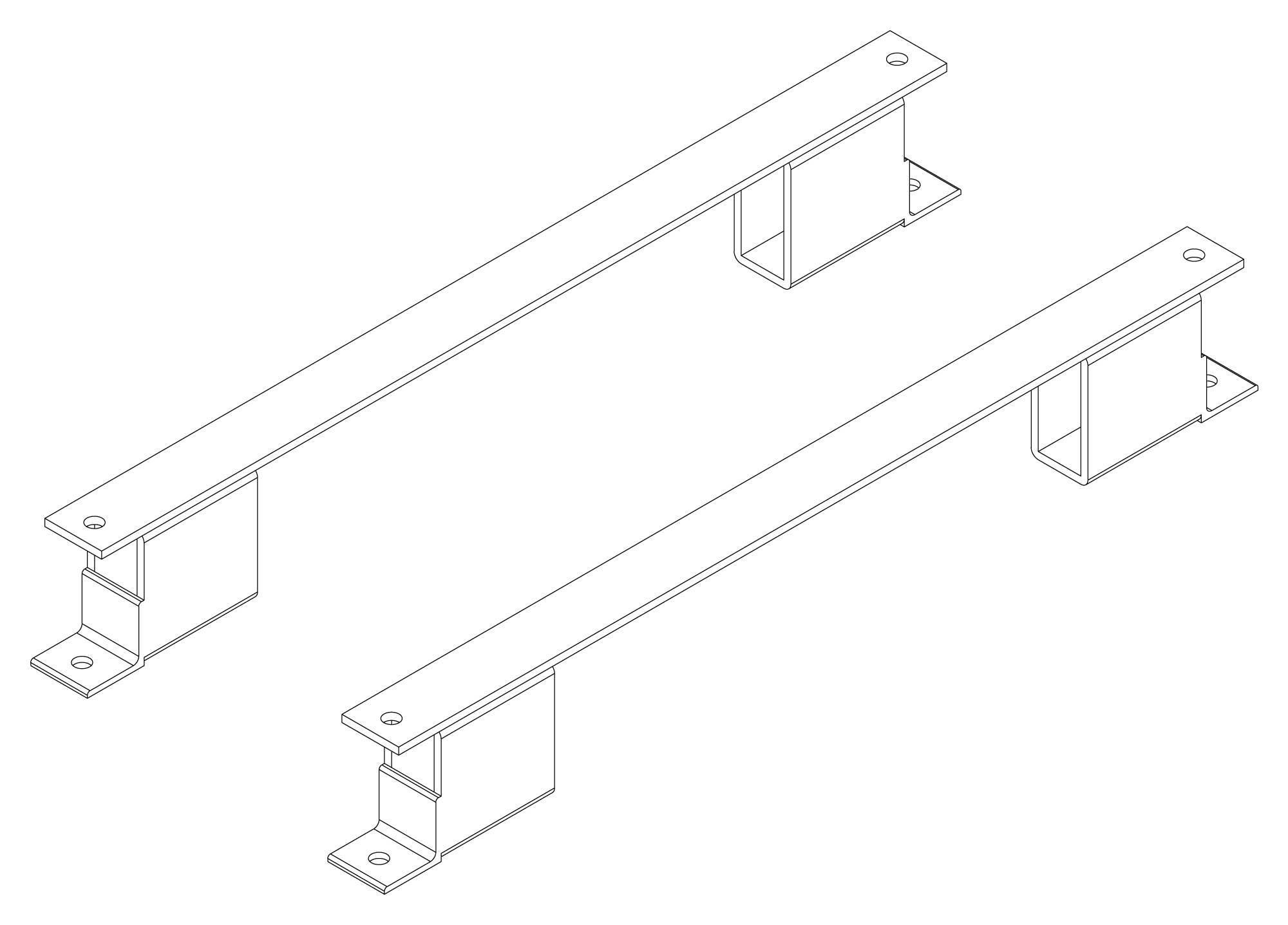
The following are vectorized diagrams for the MT Series. Refer to the Downloads section for downloadable drawings.


Integrated Options
Standard integrated options are available for Magna-Power products, allowing the product's performance and communication interfaces to be tailors to the specific application.
- Option
- +ISO
- Option
- +HS
- Option
- +GPIB
- Option
- +BD

Accessories
External accessories and integration services available for this product.