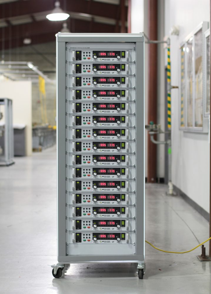
Serie XR
Programmable DC Power Supply
- Size
- 2U
- Power
- 2 kW to 10 kW
- Manufactured
- USA
- Build-time
- 6-8 weeks
La serie 2U XR complementa la serie 1U SL al proporcionar modelos de alto voltaje (más de 1500 VCC) y alta corriente (más de 250 ADC) en un paquete 2U a 2 kW, 4 kW, 6 kW, 8 kW y 10 kW. La serie XR presenta el rango de voltaje más alto en la oferta de productos de Magna-Power, hasta 10,000 VDC y modelos de alta corriente de hasta 600 dc, todos utilizando el procesamiento de potencia de corriente firme de la compañía para ofrecer una conversión de potencia robusta. Además, los niveles de programación y monitoreo de alta precisión permiten confianza en las mediciones de la fuente de alimentación, eliminando la necesidad de medidores de energía externos.

Talk with an expert


Fast, accurate power delivery with controls and options tailored to your needs
Rendimiento de alta tensión y alta corriente en 2U
Salida precisa y estable para cargas exigentes.
La Serie XR complementa la Serie SL de 1U al extenderse a modelos de 2–10 kW para alta tensión, desde 2000 Vdc hasta 10,000 Vdc, y alta corriente, desde 375 Adc hasta 600 Adc, todo en un formato compacto de 2U. En modo de tensión constante o corriente constante con cruce automático, la Serie XR ofrece una rápida recuperación de transitorios, una precisión de programación de ±0.075% para tensión y corriente, y una precisión de medición de ±0.2%, lo que permite un control y una lectura confiables sin instrumentación externa.
Configurado a pedido con opciones integradas
Características estándar completas, ampliables según las necesidades.
La Serie XR comienza con una base sólida: SCPI a través de RS232, E/S de usuario aislada de 37 pines, controladores LabVIEW e IVI, y software Remote Interface incluidos. Cuando las aplicaciones requieren más, las opciones totalmente integradas adaptan el rendimiento, la conectividad y la mecánica, sin cajas externas ni cableado improvisado.
- Controles de computadora SCPI estándar, RS232, E/S analógica/digital aislada de 37 pines, controladores LabVIEW e IVI, software RIS.
- Salida de alta velocidad de respuesta (+HS) para mayor ancho de banda y tiempos de subida programados más rápidos.
- Opciones de conectividad LXI TCP/IP Ethernet (+LXI) y IEEE-488 GPIB (+GPIB).
- Ruggedizado (+RUG) para choque y vibración según MIL-STD
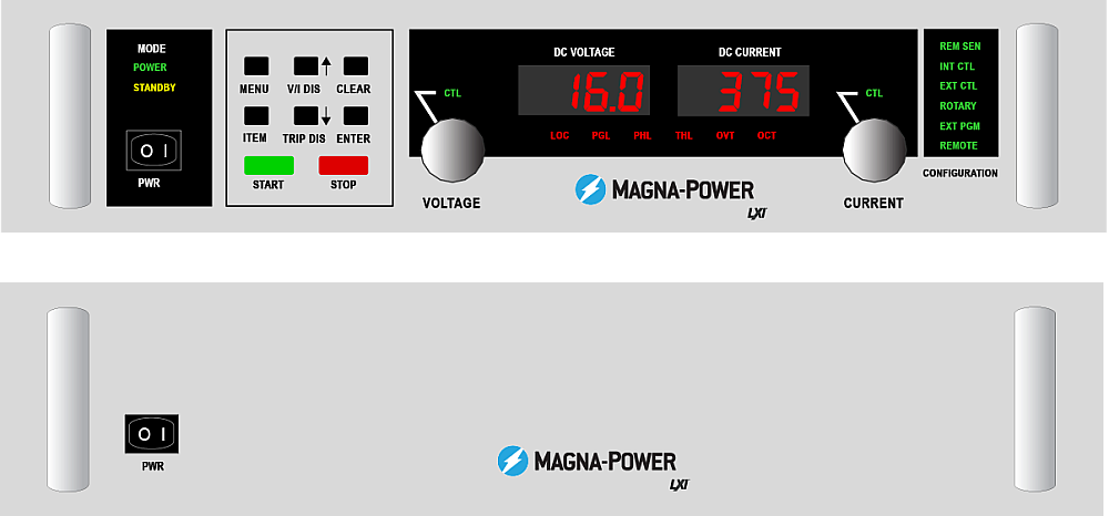
Control continuo desde el panel frontal con opción de panel en blanco
Control directo donde lo necesita, oculto donde no.
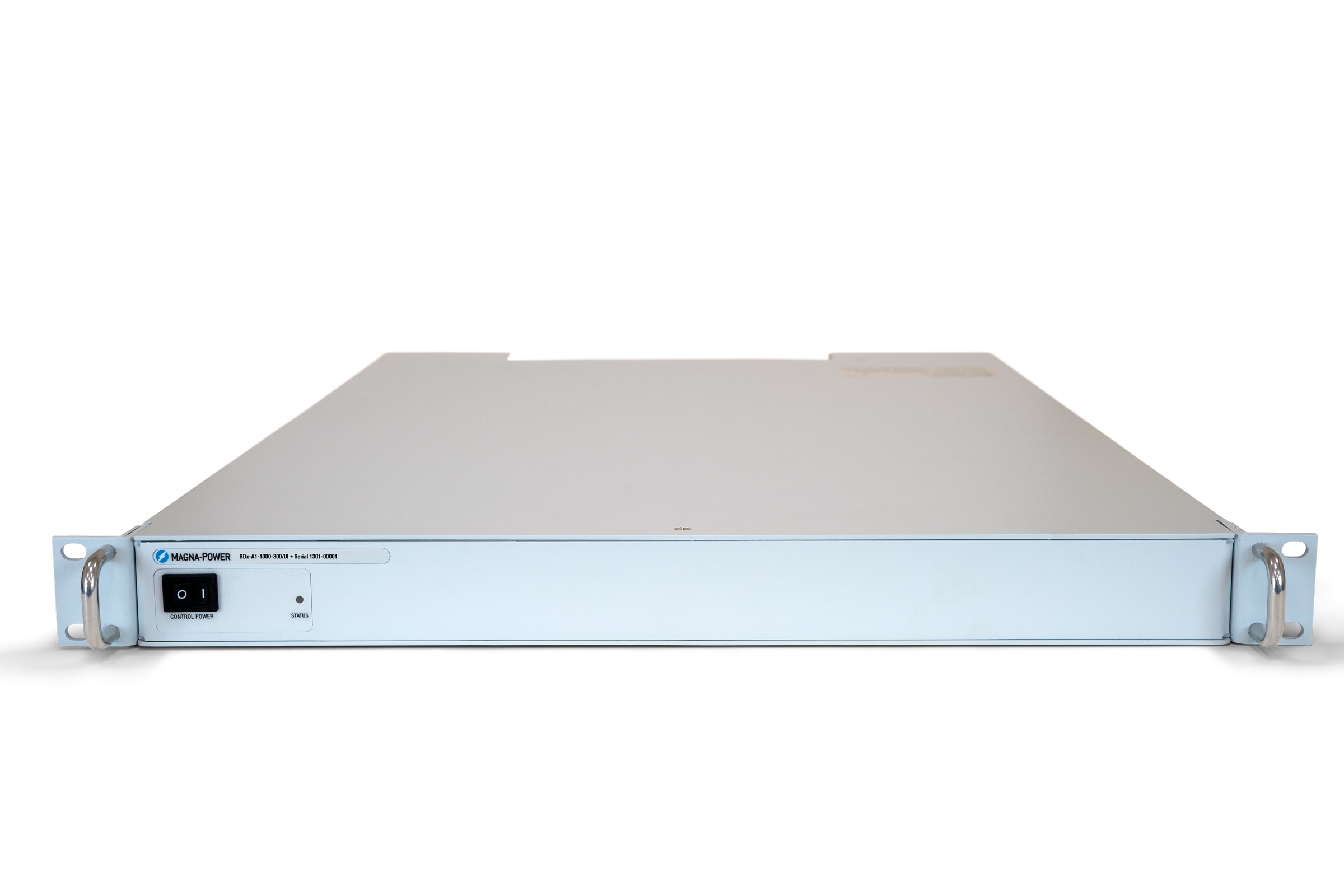
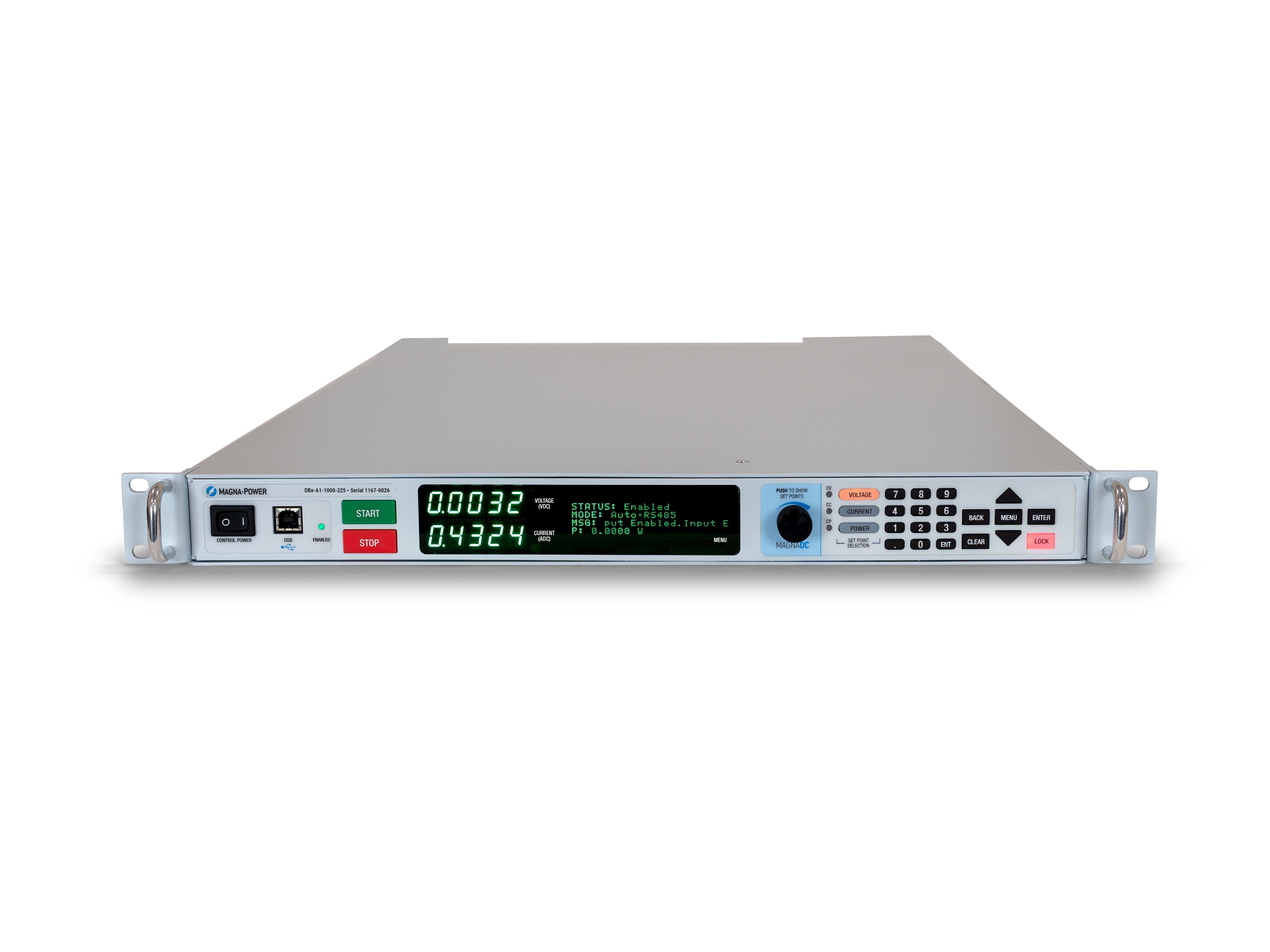
El panel frontal estándar del XR ofrece control rotativo y por teclas, medición digital de alta visibilidad e indicadores de estado claros, permitiendo a los operadores configurar puntos de ajuste, iniciar y detener la fuente, y verificar el estado del sistema de un vistazo. Para OEM y herramientas de producción, el panel frontal en blanco opcional (versión C) elimina por completo los controles locales, manteniendo el control total a través de interfaces de comunicación y el conector de E/S de usuario de 37 pines en el panel trasero, lo que mantiene los sistemas seguros, limpios y protegidos contra manipulación del operador.
Rugged by design: safety + reliability, as you'd expect from Magna-Power.

Procesamiento de potencia confiable alimentado por corriente
Robusto por diseño: topología autoprotegida para máximo tiempo de actividad.
The SLx Series uses a high-frequency, current-fed architecture that adds a control stage beyond conventional voltage-fed designs. This topology inherently limits fault energy—avoiding fast-rising current spikes and magnetic core saturation so the supply self-protects and your load stays safe. Paired with state-of-the-art SiC power semiconductors, SLx delivers class-leading power density, efficiency, and reliability, including continuous full-power operation up to 50°C ambient.
- Current-fed architecture with an added control stage vs. voltage-fed.
- Inherent surge immunity—no current spikes or core saturation.
- Self-protecting behavior under fault conditions.
- SiC devices for high density and efficiency; full power to 50°C.
Seguridad en capas, enclavamiento y parada de emergencia
Límites programables estándar más desconexión por cableado directo.
Una etapa de arranque suave mantiene la corriente de irrupción por debajo del consumo en estado estacionario, mientras que los diagnósticos integrados supervisan las condiciones de línea, térmicas e internas. Ante una falla, un disparo instantáneo (OSHT) detiene el inversor. Las fallas se reportan en la pantalla de estado del panel frontal y a través de SCPI/Modbus para una resolución rápida de problemas.
- El arranque suave limita la corriente de irrupción; el consumo de CA se mantiene por debajo de la corriente a plena carga.
- Disparos programables: sobretensión, sobrecorriente, sobrepotencia.
- Monitoreo térmico en disipador de calor y capacitores de salida.
- Entrada de enclavamiento de 5V para contacto seco, inhibición con retención (se mantiene la alimentación de control).
- Parada de emergencia de 24 V que bypasea la lógica para interrumpir la CA; desconexión completa por hardware.
From lab scripts to factory PLCs, flexible programming & integration.
Integración de software simplificada
Comandos legibles, resultados rápidos—funciona con cualquier lenguaje.
Las fuentes de alimentación MagnaDC ofrecen una API clara basada en texto con SCPI nativo, un lenguaje de comandos basado en ASCII enviado a través de comunicaciones por socket. Más de 40 comandos bien documentados cubren inicio/parada, puntos de ajuste de voltaje, corriente, mediciones de alta precisión y configuración completa—para que sus scripts y sistemas pasen del concepto a la producción rápidamente.
- Conjuntos de comandos SCPI con comportamiento consistente.
- Inicio/parada y protecciones: habilitar salida, establecer límites de disparo, consultar estado.
- Lecturas de alta precisión: voltaje, corriente, potencia y retroalimentación de sensor.
- Documentación y ejemplos orientados al desarrollador.
import serial
magnaPower = serial.Serial(port='COM4', baudrate=19200)
magnaPower.write('*IDN?\n'.encode())
print magna_power.readline()
magnaPower.write('VOLT 0\n'.encode())
magnaPower.write('CURR 0\n'.encode())
magnaPower.write('OUTP:START\n'.encode())
magnaPower.write('VOLT 270\n'.encode())
currSetPoints = [50, 100, 150, 250]
for currSetPoint in currSetPoints:
    print 'Setting Current to %s A' % currSetPoint
    magnaPower.write('CURR {0}\n'.format(currSetPoint).encode())
    magnaPower.write('MEAS:VOLT?\n'.encode())
    print magnaPower.readline()
    time.sleep(20)
magnaPower.write('OUTP:STOP\n'.encode())
magnaPower.close()
magna_power = serial('COM4', 'BaudRate', 19200);
fopen(magnaPower);
fprintf(magnaPower,'*IDN?');
idn = fscanf(magnaPower);
fprintf(magnaPower,'VOLT 0');
fprintf(magnaPower,'CURR 0');
fprintf(magnaPower,'OUTP:START');
fprintf(magnaPower,'VOLT 270');
for currSetPoint in [50, 100, 150, 250]
    display('Setting Current to '+currSetPoint+' A');
    fprintf(magnaPower, 'CURR '+currSetPoint);
    fprintf(magnaPower,'MEAS:VOLT?');
    display(fscanf(magnaPower));
    pause(20);
end
#include <stdio.h>
#include <stdint.h>
#include <string.h>
#include <windows.h>

int main()
{
    printf("Opening connection.\n");

    uint8_t recvBuffer[sizeof(uint8_t) * 256];
    memset(recvBuffer, 0, 256);

    // Choose the serial port name.
    // COM ports higher than COM9 need the \\.\ prefix, which is written as
    // "\\\\.\\" in C because we need to escape the backslashes.
    const char* device = "\\\\.\\COM4";

    // Choose the baud rate (bits per second).
    uint32_t baud_rate = 19200;

    HANDLE port = open_serial_port(device, baud_rate);
    if (port == INVALID_HANDLE_VALUE) { return 1; }

    char* scpiCmd = (char*)"*IDN?\n";
    size_t cmdLen = strlen(scpiCmd);
    int result = write_port(port, (uint8_t*)scpiCmd, cmdLen);
    if (result < 0)
        return -1;

    result = read_port(port, recvBuffer, 256);
    printf("Sent: %s\nReceived: %s\n", scpiCmd, recvBuffer);

    scpiCmd = (char*)"VOLT 0\n";
    cmdLen = strlen(scpiCmd);
    result = write_port(port, (uint8_t*)scpiCmd, cmdLen);
    if (result < 0)
        return -1;

    scpiCmd = (char*)"CURR 0\n";
    cmdLen = strlen(scpiCmd);
    result = write_port(port, (uint8_t*)scpiCmd, cmdLen);
    if (result < 0)
        return -1;

    scpiCmd = (char*)"OUTP:START\n";
    cmdLen = strlen(scpiCmd);
    result = write_port(port, (uint8_t*)scpiCmd, cmdLen);
    if (result < 0)
        return -1;

    scpiCmd = (char*)"VOLT 270\n";
    cmdLen = strlen(scpiCmd);
    result = write_port(port, (uint8_t*)scpiCmd, cmdLen);
    if (result < 0)
        return -1;

    char setPoints[4][5] = {"50", "100", "150", "200"};
    char setPointBuffer[40];
    scpiCmd = (char*)"MEAS:VOLT?\n";

    for (int i = 0; i < 4; i++)
    {
        sprintf(setPointBuffer, "CURR %s\n", setPoints[i]);
        printf("Setting current to %s A\n", setPoints[i]);
        cmdLen = strlen(setPointBuffer);
        result = write_port(port, (uint8_t*)setPointBuffer, cmdLen);
        if (result < 0)
            return -1;
        memset(recvBuffer, 0, 256);
        result = read_port(port, recvBuffer, 256);
        printf("Received: %s\n", recvBuffer);
        Sleep(20000);  // 20000ms = 20s
    }

    scpiCmd = (char*)"OUTP:STOP\n";
    cmdLen = strlen(scpiCmd);
    result = write_port(port, (uint8_t*)scpiCmd, cmdLen);
    if (result < 0)
        return -1;

    CloseHandle(port);

    printf("Connection closed.\n");
    return 0;
}
using System;
using System.IO.Ports;
using System.Threading;

namespace SerialCommunicationInCSharp
{
  public class Program
  {
    static bool _continue;
    static SerialPort serialPort;

    public static void Main(string[] args)
    {
      Thread readThread = new Thread(Read);

      Console.WriteLine("Opening connection.");

      // Create a new SerialPort object with default settings.
      serialPort = new SerialPort("COM4", 19200, Parity.None, 8, StopBits.One);

      // Set the read/write timeouts
      serialPort.ReadTimeout = 500;
      serialPort.WriteTimeout = 500;

      serialPort.Open();
      _continue = true;
      readThread.Start();

      Console.WriteLine("Sending: *IDN?");
      serialPort.WriteLine("*IDN?");

      serialPort.WriteLine("VOLT 0");
      serialPort.WriteLine("CURR 0");
      serialPort.WriteLine("OUTP:START");
      serialPort.WriteLine("VOLT 270");

      string[] currSetPoints = { "50", "100", "150", "250" };
ß
      for(int i = 0; i < currSetPoints.Length; i++)
      {
        serialPort.WriteLine(String.Format("'CURR {0}", currSetPoints[i]));
        serialPort.WriteLine("MEAS:VOLT?");
        Thread.Sleep(20000);
      }

      serialPort.WriteLine("OUTP:STOP");

      Console.WriteLine("Closing connection.");
      _continue = false;
      serialPort.Close();
      }

    public static void Read()
    {
      while (_continue)
      {
        try
        {
          string message = serialPort.ReadLine();
          Console.WriteLine("Received: " + message);
        }
        catch (TimeoutException) { }
      }
    }
  }
}

E/S de usuario externa para control PLC o simulación PHIL
Conéctelo como un módulo de E/S, sin necesidad de aislamiento adicional.
Via the included rear 37-pin User I/O connector, MagnaDC supplies can be fully driven and monitored by external signals or a PLC. Voltage, current, OVT, and OCT set points are programmed with 0–10 V analog inputs, while each diagnostic condition has its own +5V digital status pin. Built-in +2.5V, +5V, and +10V reference rails let you use dry contacts without adding external supplies. All I/O is isolated from the output and referenced to earth ground as standard.
-
0–10 V analog programming for V, I, OVT, and OCT.
-
Per-fault digital outputs: each diagnostic has its own +5V pin.
-
Isolated user I/O referenced to earth ground—no extra isolators.
-
With High Slew Rate Output (+HS), high-bandwidth response and fast rise times support HIL/PHIL simulation applications.
Operación maestro-esclavo de alto rendimiento
Escale voltaje o corriente sin sacrificar rendimiento.
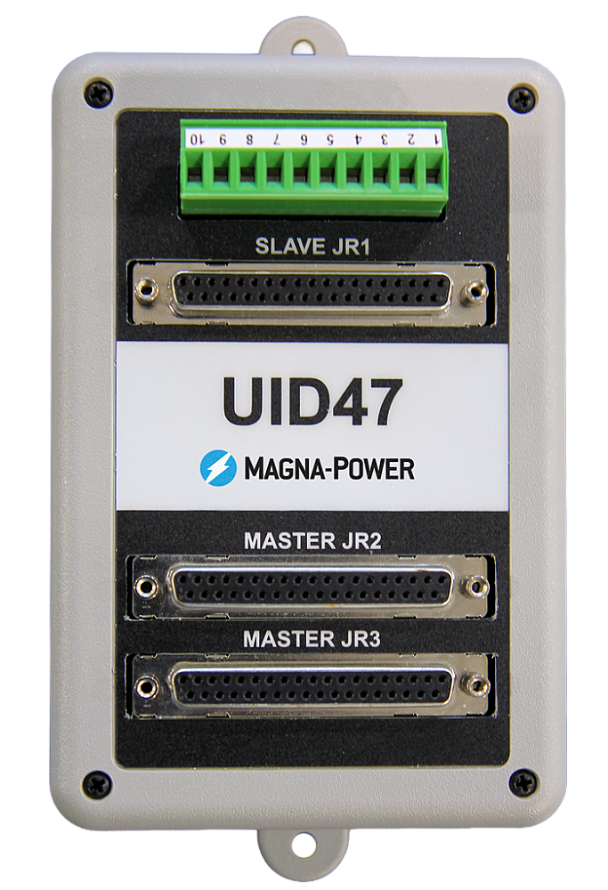
All MagnaDC supplies support master-slave operation, using gate-drive signals from the master when configured for parallel, so the whole stack behaves like a single supply—with one control loop and no noisy long analog references. The optional UID47 accessory simplifies wiring for series or parallel sets with near-equal sharing.
-
Single control loop parallel operation: Master gate-drive to slaves for consistent dynamics.
-
Plug & play with the UID47, enabling parallel or series stacks with current/voltage sharing.
-
Series up to the DC isolation rating without added hardware.
No additional ORing diodes required for parallel operation.
Software, controladores LabVIEW e IVI de Magna-Power
Del panel frontal virtual a la automatización completa, listo para usar.
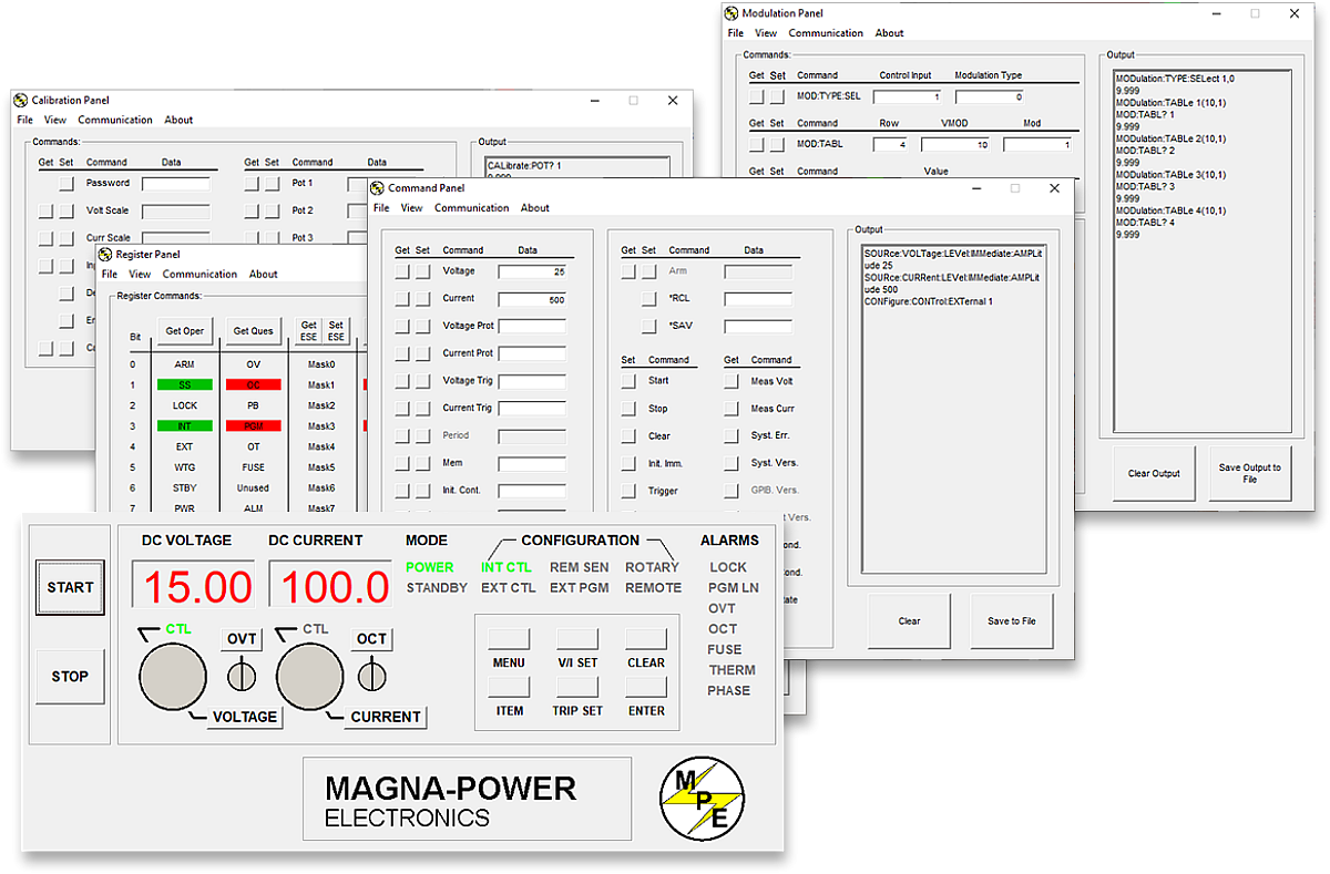
Cada fuente MagnaDC incluye un controlador IVI y un controlador NI LabVIEW con un conjunto completo de VIs, además de programas de ejemplo para que pueda comunicarse con el hardware en minutos. Para el control directo estilo panel frontal desde una PC, el software de interfaz remota de Magna-Power ofrece una vista completa de la fuente, desde comandos y registros hasta calibración y firmware.
-
Controladores IVI y NI LabVIEW incluidos con conjunto completo de VIs.
-
Programas de ejemplo para acelerar la integración y las pruebas.
-
Software de interfaz remota con:
-
Panel frontal virtual para control manual
-
Panel de comandos para explorar y enviar comandos
-
Panel de registros para monitoreo de estado en tiempo real
-
Panel de calibración para potenciómetros digitales internos
-
Panel de firmware para actualizaciones en sitio
-
Panel de modulación para emular perfiles no lineales
-
-
Todas las interfaces de comunicación compatibles con el software y los controladores para una experiencia de programación consistente.
State-of-the-art USA manufacturing with worldwide support

Made in the USA
Fabricación verticalmente integrada para un control de calidad total.
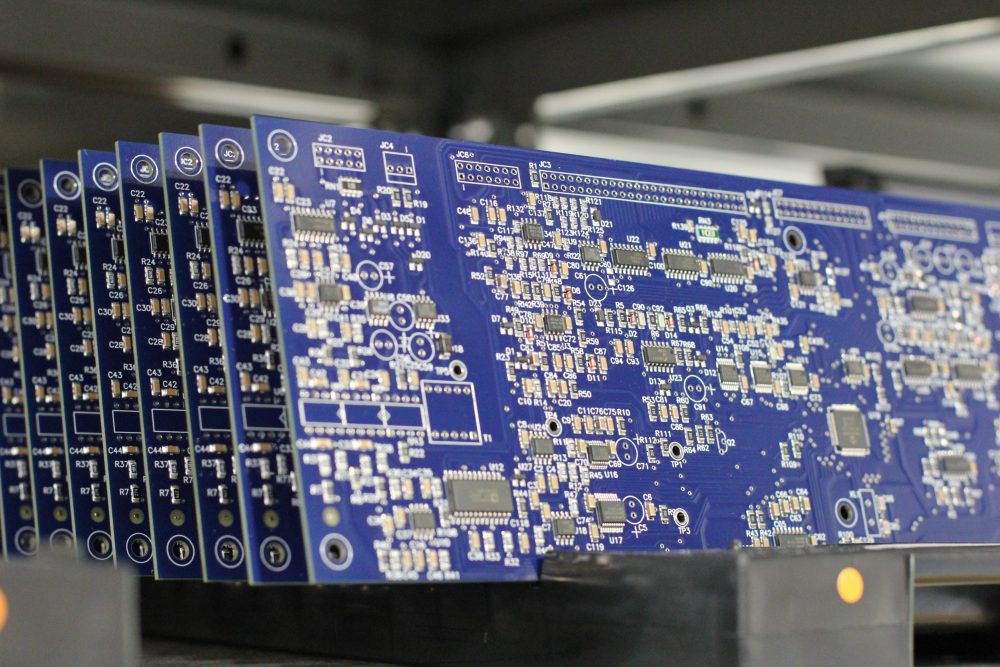
Los productos de Magna-Power se diseñan, fabrican, prueban y reciben servicio en la sede central de Magna-Power de 73,500 sq-ft en Flemington, New Jersey, donde el trabajo en metal, los magnéticos, el ensamblaje de PCB y el rodaje se realizan internamente para un control riguroso de la calidad, los costos y los tiempos de entrega.
- Fabricado en EE. UU.: Ingeniería, manufactura y servicio bajo un mismo techo.
- Producción interna: Trabajo en metal, magnéticos, PCBs SMT y acabados.
- Fiabilidad comprobada: Cada unidad completamente probada, calibrada y sometida a rodaje.
Servicio mundial y soporte de piezas OEM
Experiencia de fábrica, respuesta local.
Magna-Power respalda sus productos con centros de servicio de fábrica y autorizados en América del Norte, Europa, el Reino Unido, Asia-Pacífico, Asia Oriental y América del Sur, utilizando procedimientos de fábrica y piezas originales para restaurar las unidades a sus especificaciones originales, dentro o fuera de garantía.
- Cobertura global: sede central en Nueva Jersey más centros de servicio autorizados regionales.
- Reparaciones consistentes: diagnósticos de fábrica, instrucciones de trabajo y diagramas del sistema.
- Piezas OEM originales: ensamblajes de repuesto probados para un servicio predecible y con mínimo tiempo de inactividad.
Model Ordering Guide
For both ordering and production, XR Series models are uniquely defined by several key characteristics, as defined by the following diagram:

XR Series Models
There are 39 different models in the XR Series spanning power levels: 2 kW, 4 kW, 6 kW, 8 kW, 10 kW. To determine the appropriate model:
- Select the desired Max Voltage (Vdc) from the left-most column.
- Select the desired Max Current (Adc) from the same row that contains your desired Max Voltage.
- Construct your model number according to the model ordering guide.
| Max Voltage Vdc |
2 kW | 4 kW | 6 kW | 8 kW | 10 kW | Ripple mVrms |
Efficiency |
|---|---|---|---|---|---|---|---|
| Max Current Adc | |||||||
| 5 | 375 | 600 | — | — | — | 50 | 80% |
| 10 | — | 375 | 600 | — | — | 50 | 84% |
| 16 | — | — | 375 | 500 | 600 | 50 | 84% |
| 20 | — | — | 300 | 375 | 500 | 45 | 87% |
| 25 | — | — | — | 320 | 400 | 45 | 88% |
| 32 | — | — | — | — | 310 | 40 | 88% |
| 2000 | 1 | 2 | 3 | 4 | 5 | 500 | 93% |
| 3000 | 0.6 | 1.3 | 2 | 2.6 | 3.3 | 600 | 93% |
| 4000 | 0.5 | 1 | 1.5 | 2 | — | 6500 | 93% |
| 6000 | 0.33 | 0.66 | 1 | 1.33 | — | 7500 | 93% |
| 8000 | 0.25 | 0.5 | 0.75 | 1 | — | 8500 | 93% |
| 10000 | 0.2 | 0.4 | 0.6 | 0.8 | — | 9500 | 93% |
| AC Input Voltage Vac |
Input Current Per Phase Aac | ||||||
| 208/240 Vac, 1Φ | 17 | — | — | — | — | ||
| 208/240 Vac, 3Φ | 8 | 15 | 22 | 29 | 35 | ||
| 380/415 Vac, 3Φ | 5 | 9 | 12 | 16 | 19 | ||
| 440/480 Vac, 3Φ | 4 | 8 | 11 | 14 | 17 | ||
Specifications are subject to change without notice. Unless otherwise noted, all specifications measured at the product's maximum ratings.
AC Input Specifications
240 Vac (operating range 216 - 264 Vac)
240 Vac (operating range 216 to 264 Vac)
380 Vac (operating range 342 to 440 Vac)
415 Vac (operating range 373 to 456 Vac)
440 Vac (operating range 396 to 484 Vac)
480 Vac (operating range 432 to 528 Vac)
0.70 at max power; models with 1Φ AC input
DC Output Specifications
Current mode: ± 0.02% of full scale
Current mode: ± 0.04% of full scale
Model specific. Refer to chart of available models.
< 200 ms for a programmed output current change from 0 to 63%
< 10 ms for an output current change from 0 to 63%
2 Hz with remote analog current programming
45 Hz with remote analog current programming
Programming Interface Specifications
LXI TCP/IP Ethernet RJ45 (Option +LXI)
IEEE-488 GPIB (Option +GPIB)
Referenced to Earth ground; isolated from power supply output
See User Manual for pin layout
Accuracy Specifications
External User I/O Specifications
Current output monitoring: 100 Ω
+10V reference: 1 Ω
Output: 0 to 5 Vdc, 5 mA drive capacity
Physical Specifications
3.50" H x 19" W x 24" D (8.89 x 48.26 x 60.96 cm)
45 lbs (20.41 kg)
3.50" H x 19" W x 24" D (8.89 x 48.26 x 60.96 cm)
47 lbs (21.32 kg)
3.50" H x 19" W x 24" D (8.89 x 48.26 x 60.96 cm)
48 lbs (21.77 kg)
3.50" H x 19" W x 24" D (8.89 x 48.26 x 60.96 cm)
48 lbs (21.77 kg)
3.50" H x 19" W x 24" D (8.89 x 48.26 x 60.96 cm)
48 lbs (21.77 kg)
Environmental Specifications
0.06%/°C of maximum output current
Regulatory Specifications
CISPR 22 / EN 55022 Class A
The following are vectorized diagrams for the XR Series. Refer to the Downloads section for downloadable drawings.


Integrated Options
Standard integrated options are available for Magna-Power products, allowing the product's performance and communication interfaces to be tailors to the specific application.
- Option
- +HS
- Option
- +GPIB

Accessories
External accessories and integration services available for this product.