Serie ALx
DC Electronic Load
- Size
- 3U to 24U
- Power
- 1.25 kW to 20 kW
- Manufactured
- USA
- Build-time
- 6-8 weeks
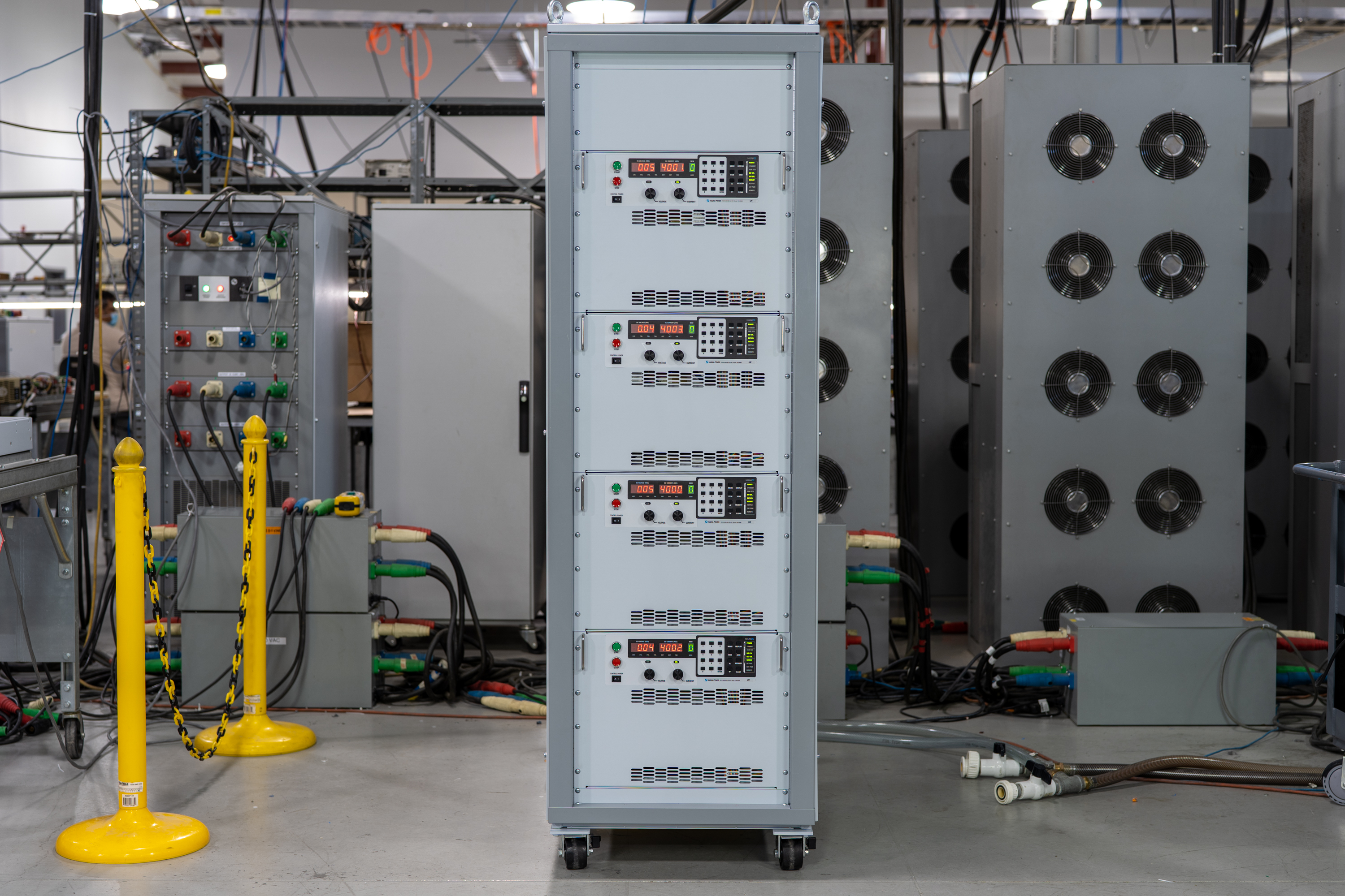
The ALx Series MagnaLOAD utilizes conventional linear MOSFET-based dissipative elements, allowing the series to achieve a very wide voltage-current operating range within the model’s maximum power rating. Using the same heat management innovations developed for Magna-Power’s high density programmable DC power supplies, the ALx Series’ conservative cooling ensures long product life with continuous full power operation in environments up to 50°C ambient operating temperature.

Talk with an expert
Do more with MagnaLINK™ distributed digital control.

Control y medición de precisión
Precisión impulsada por DSP desde el punto de ajuste hasta el punto de carga.
La Serie SLx cuenta con la plataforma de control digital xGen MagnaLINK™ de Magna-Power, que utiliza una red distribuida de DSPs y comunicaciones de alta velocidad entre placas mediante un protocolo de comunicación de bajo nivel desarrollado internamente. La programación interna de ganancias con ganancias ajustables en campo admite una amplia gama de condiciones de carga.
- Control de voltaje, corriente y potencia con resolución de 16 bits.
- Controles programables de velocidad de respuesta.
- Estabilidad nativa de 100 ppm.
- Detección de voltaje local, remota y sin cables para una regulación precisa en el punto de carga.

Master-slaving plug-and-play
Escale la potencia sin interrupciones con clasificaciones de sistema agregadas.
Los puertos duales MagnaLINK proporcionan master-slaving digital-híbrido de última generación, permitiendo que una unidad controle un conjunto sincronizado. Amplíe la capacidad de corriente conectando en paralelo hasta 16 unidades. Una conexión secundaria de detección de corriente proporciona corriente analógica en tiempo real al maestro para una agregación y visualización precisas.
- Conexión en paralelo de hasta 16 unidades con cableado de interfaz sencillo.
- Un solo punto de ajuste; salida y protecciones sincronizadas.
- Retroalimentación secundaria de detección de corriente para un reparto preciso.
- Autoconfiguración y mediciones agregadas en una única pantalla maestra.
From lab scripts to factory PLCs, flexible programming & integration.
Integración de software simplificada
Comandos legibles, resultados rápidos—funciona con cualquier lenguaje.
La serie SLx ofrece una API clara basada en texto con SCPI y Modbus nativos. Más de 60 comandos bien documentados cubren inicio/parada, puntos de ajuste para voltaje, corriente y potencia, control de velocidad de respuesta, mediciones de alta precisión y configuración completa—para que sus scripts y sistemas pasen del concepto a la producción rápidamente.
- Conjuntos de comandos SCPI y Modbus con comportamiento consistente.
- Inicio/parada y protecciones: habilitar salida, establecer límites de disparo, consultar estado.
- Lecturas de alta precisión: voltaje, corriente, potencia y retroalimentación de sensor.
- Documentación y ejemplos orientados al desarrollador.
import serial
magnaPower = serial.Serial(port='COM4', baudrate=115200)
magnaPower.write('*IDN?\n'.encode())
print magna_power.readline()
magnaPower.write('VOLT 0\n'.encode())
magnaPower.write('CURR 0\n'.encode())
magnaPower.write('OUTP:START\n'.encode())
magnaPower.write('VOLT 270\n'.encode())
currSetPoints = [50, 100, 150, 250]
for currSetPoint in currSetPoints:
    print 'Setting Current to %s A' % currSetPoint
    magnaPower.write('CURR {0}\n'.format(currSetPoint).encode())
    magnaPower.write('MEAS:VOLT?\n'.encode())
    print magnaPower.readline()
    time.sleep(20)
magnaPower.write('OUTP:STOP\n'.encode())
magnaPower.close()
magna_power = serial('COM4', 'BaudRate', 115200);
fopen(magnaPower);
fprintf(magnaPower,'*IDN?');
idn = fscanf(magnaPower);
fprintf(magnaPower,'VOLT 0');
fprintf(magnaPower,'CURR 0');
fprintf(magnaPower,'OUTP:START');
fprintf(magnaPower,'VOLT 270');
for currSetPoint in [50, 100, 150, 250]
    display('Setting Current to '+currSetPoint+' A');
    fprintf(magnaPower, 'CURR '+currSetPoint);
    fprintf(magnaPower,'MEAS:VOLT?');
    display(fscanf(magnaPower));
    pause(20);
end
#include <stdio.h>
#include <stdint.h>
#include <string.h>
#include <windows.h>

int main()
{
    printf("Opening connection.\n");

    uint8_t recvBuffer[sizeof(uint8_t) * 256];
    memset(recvBuffer, 0, 256);

    // Choose the serial port name.
    // COM ports higher than COM9 need the \\.\ prefix, which is written as
    // "\\\\.\\" in C because we need to escape the backslashes.
    const char* device = "\\\\.\\COM4";

    // Choose the baud rate (bits per second).
    uint32_t baud_rate = 115200;

    HANDLE port = open_serial_port(device, baud_rate);
    if (port == INVALID_HANDLE_VALUE) { return 1; }

    char* scpiCmd = (char*)"*IDN?\n";
    size_t cmdLen = strlen(scpiCmd);
    int result = write_port(port, (uint8_t*)scpiCmd, cmdLen);
    if (result < 0)
        return -1;

    result = read_port(port, recvBuffer, 256);
    printf("Sent: %s\nReceived: %s\n", scpiCmd, recvBuffer);

    scpiCmd = (char*)"VOLT 0\n";
    cmdLen = strlen(scpiCmd);
    result = write_port(port, (uint8_t*)scpiCmd, cmdLen);
    if (result < 0)
        return -1;

    scpiCmd = (char*)"CURR 0\n";
    cmdLen = strlen(scpiCmd);
    result = write_port(port, (uint8_t*)scpiCmd, cmdLen);
    if (result < 0)
        return -1;

    scpiCmd = (char*)"OUTP:START\n";
    cmdLen = strlen(scpiCmd);
    result = write_port(port, (uint8_t*)scpiCmd, cmdLen);
    if (result < 0)
        return -1;

    scpiCmd = (char*)"VOLT 270\n";
    cmdLen = strlen(scpiCmd);
    result = write_port(port, (uint8_t*)scpiCmd, cmdLen);
    if (result < 0)
        return -1;

    char setPoints[4][5] = {"50", "100", "150", "200"};
    char setPointBuffer[40];
    scpiCmd = (char*)"MEAS:VOLT?\n";

    for (int i = 0; i < 4; i++)
    {
        sprintf(setPointBuffer, "CURR %s\n", setPoints[i]);
        printf("Setting current to %s A\n", setPoints[i]);
        cmdLen = strlen(setPointBuffer);
        result = write_port(port, (uint8_t*)setPointBuffer, cmdLen);
        if (result < 0)
            return -1;
        memset(recvBuffer, 0, 256);
        result = read_port(port, recvBuffer, 256);
        printf("Received: %s\n", recvBuffer);
        Sleep(20000);  // 20000ms = 20s
    }

    scpiCmd = (char*)"OUTP:STOP\n";
    cmdLen = strlen(scpiCmd);
    result = write_port(port, (uint8_t*)scpiCmd, cmdLen);
    if (result < 0)
        return -1;

    CloseHandle(port);

    printf("Connection closed.\n");
    return 0;
}
using System;
using System.IO.Ports;
using System.Threading;

namespace SerialCommunicationInCSharp
{
  public class Program
  {
    static bool _continue;
    static SerialPort serialPort;

    public static void Main(string[] args)
    {
      Thread readThread = new Thread(Read);

      Console.WriteLine("Opening connection.");

      // Create a new SerialPort object with default settings.
      serialPort = new SerialPort("COM4", 115200, Parity.None, 8, StopBits.One);

      // Set the read/write timeouts
      serialPort.ReadTimeout = 500;
      serialPort.WriteTimeout = 500;

      serialPort.Open();
      _continue = true;
      readThread.Start();

      Console.WriteLine("Sending: *IDN?");
      serialPort.WriteLine("*IDN?");

      serialPort.WriteLine("VOLT 0");
      serialPort.WriteLine("CURR 0");
      serialPort.WriteLine("OUTP:START");
      serialPort.WriteLine("VOLT 270");

      string[] currSetPoints = { "50", "100", "150", "250" };
ß
      for(int i = 0; i < currSetPoints.Length; i++)
      {
        serialPort.WriteLine(String.Format("'CURR {0}", currSetPoints[i]));
        serialPort.WriteLine("MEAS:VOLT?");
        Thread.Sleep(20000);
      }

      serialPort.WriteLine("OUTP:STOP");

      Console.WriteLine("Closing connection.");
      _continue = false;
      serialPort.Close();
      }

    public static void Read()
    {
      while (_continue)
      {
        try
        {
          string message = serialPort.ReadLine();
          Console.WriteLine("Received: " + message);
        }
        catch (TimeoutException) { }
      }
    }
  }
}

E/S de usuario externo
Controles analógico-digitales aislados y flexibles.
Todas las fuentes de alimentación de la Serie SLx incluyen de serie un conector D-Sub de 26 pines designado como E/S de usuario externo. Este conector proporciona:
- 8 salidas digitales (lógica de 5V)
- 4 entradas digitales (lógica de 5V)
- 4 salidas analógicas (lógica de 0-10V)
- 4 entradas analógicas (lógica de 0-10V)
La E/S de usuario externo está aislada de los terminales de salida y referenciada a tierra. Los pines del conector son configurables por el usuario, lo que permite seleccionar las funciones necesarias para su aplicación, al tiempo que ofrece capacidad futura para nuevas características. Utilice las salidas digitales para integrar la fuente de alimentación con, por ejemplo, señales de habilitación externas o lógica de monitoreo de fallas digitales, o monitoree el voltaje-corriente utilizando las salidas analógicas de 0-10V. También se proporciona una entrada analógica dedicada de alta velocidad, muestreada a 2 kHz para un control casi en tiempo real.
Comunicaciones y control industrial
De redes de laboratorio a PLCs: integre en sus propios términos.
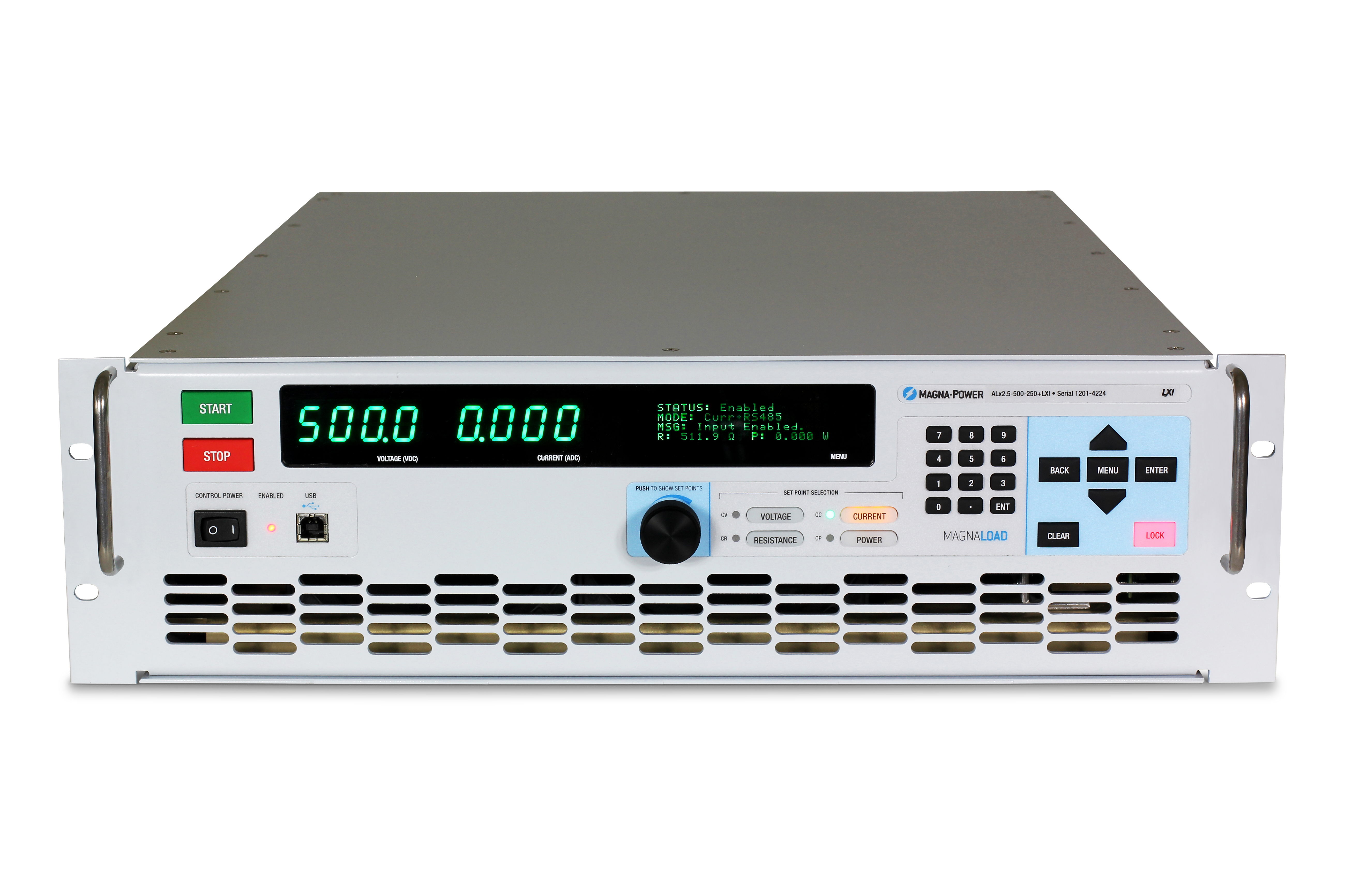
La Serie se entrega lista para conectar con USB dual (frontal y trasero) y RS485, con soporte para SCPI y Modbus. Para redes y automatización industrial, elija opciones totalmente integradas con soporte Modbus, documentación completa y archivos de descripción de dispositivos para agilizar la configuración del PLC y el mapeo de etiquetas.
- USB dual estándar (frontal + trasero) y RS485.
- Red TCP/IP con la opción LXI TCP/IP Ethernet (+LXI)
- Opciones de buses de campo para PLC: CANopen (+CAN), EtherCAT (+ECAT), EtherNet/IP (+EIP), Modbus-TCP (+MTCP), PROFINET (+PROF).
- Archivos de dispositivos incluidos: EDS (CANopen/EtherNet/IP), ESI XML (EtherCAT), GSDML (PROFINET) para una rápida integración con PLC.
- Documentación completa de comandos, ejemplos y diagnósticos.
Software MagnaCTRL incluido
Control de panel multi-producto, diagnósticos y actualizaciones—listos para usar.
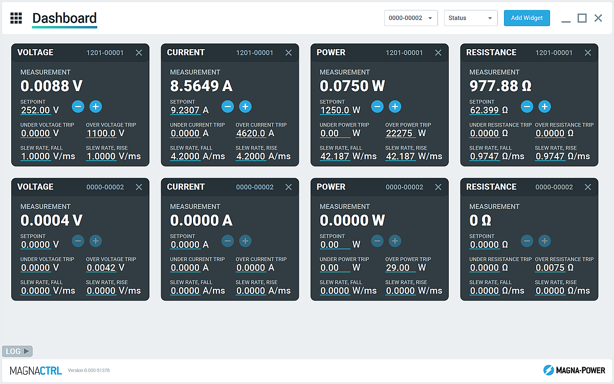
MagnaCTRL es una plataforma de control multi-producto moderna incluida con los productos xGen. Cree paneles de control, configure E/S, ejecute actualizaciones y acceda a diagnósticos avanzados—todo desde una sola aplicación.
- Panel configurable: agregue/organice widgets para monitorear y controlar múltiples unidades conectadas.
- Explorador de productos: detecte dispositivos automáticamente, guarde conexiones y reconéctese automáticamente en futuras sesiones.
- Panel de E/S de usuario externo: mapee E/S de 26 pines, exporte/importe mapas de pines para despliegues rápidos.
- Actualizaciones de firmware/software: detecte nuevas versiones automáticamente; realice actualizaciones manuales sin conexión si es necesario (consulte el Registro de cambios)
- Herramientas de calibración: ajuste ganancias/offsets de programación/medición; con orientación, ajuste las ganancias del lazo de control.
- Registro de datos: salida gráfica y registro .csv de mediciones y configuraciones de voltaje, corriente y potencia a lo largo del tiempo
State-of-the-art USA manufacturing with worldwide support

Made in the USA
Fabricación verticalmente integrada para un control de calidad total.
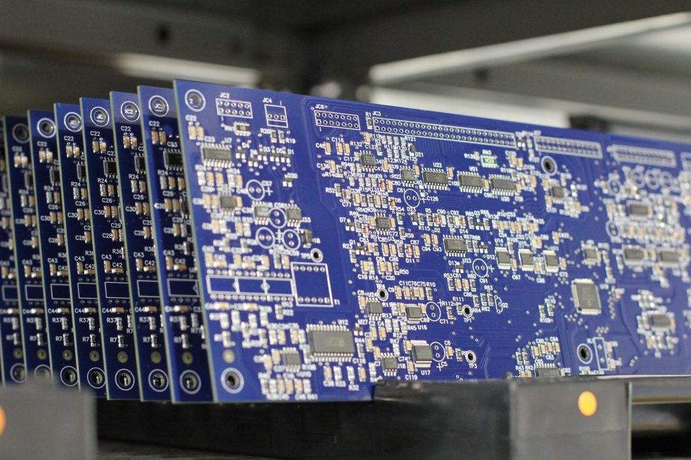
Los productos de Magna-Power se diseñan, fabrican, prueban y reciben servicio en la sede central de Magna-Power de 73,500 sq-ft en Flemington, New Jersey, donde el trabajo en metal, los magnéticos, el ensamblaje de PCB y el rodaje se realizan internamente para un control riguroso de la calidad, los costos y los tiempos de entrega.
- Fabricado en EE. UU.: Ingeniería, manufactura y servicio bajo un mismo techo.
- Producción interna: Trabajo en metal, magnéticos, PCBs SMT y acabados.
- Fiabilidad comprobada: Cada unidad completamente probada, calibrada y sometida a rodaje.
Servicio mundial y soporte de piezas OEM
Experiencia de fábrica, respuesta local.
Magna-Power respalda sus productos con centros de servicio de fábrica y autorizados en América del Norte, Europa, el Reino Unido, Asia-Pacífico, Asia Oriental y América del Sur, utilizando procedimientos de fábrica y piezas originales para restaurar las unidades a sus especificaciones originales, dentro o fuera de garantía.
- Cobertura global: sede central en Nueva Jersey más centros de servicio autorizados regionales.
- Reparaciones consistentes: diagnósticos de fábrica, instrucciones de trabajo y diagramas del sistema.
- Piezas OEM originales: ensamblajes de repuesto probados para un servicio predecible y con mínimo tiempo de inactividad.
Model Ordering Guide
For both ordering and production, ALx Series models are uniquely defined by several key characteristics, as defined by the following diagram:

ALx Series Models
There are 27 different models in the ALx Series spanning power levels: 1.25 kW, 2.5 kW, 5 kW, 7.5 kW, 10 kW, 12.5 kW, 15 kW, 17.5 kW, 20 kW. To determine the appropriate model:
- Select the desired Max Voltage (Vdc) from the left-most column.
- Select the desired Max Current (Adc) from the same row that contains your desired Max Voltage.
- Construct your model number according to the model ordering guide.
| Model | Max Power kW |
Max Voltage Vdc |
Max Current Adc |
Package Type | Min Voltage Vdc |
Max Resistance Ω |
|---|---|---|---|---|---|---|
| ALx1.25-200-300 | 1.25 | 200 | 300 | Rack-mount | 2.5 | 70.40 |
| ALx1.25-500-125 | 1.25 | 500 | 125 | Rack-mount | 6.0 | 448.00 |
| ALx1.25-1000-37.5 | 1.25 | 1000 | 37.5 | Rack-mount | 7.5 | 1792.00 |
| ALx2.5-200-600 | 2.5 | 200 | 600 | Rack-mount | 2.5 | 70.40 |
| ALx2.5-500-250 | 2.5 | 500 | 250 | Rack-mount | 6.0 | 448.00 |
| ALx2.5-1000-75 | 2.5 | 1000 | 75 | Rack-mount | 7.5 | 1792.00 |
| ALx5-200-1200 | 5 | 200 | 1200 | Floor-standing | 2.5 | 35.20 |
| ALx5-500-500 | 5 | 500 | 500 | Floor-standing | 6.0 | 224.00 |
| ALx5-1000-150 | 5 | 1000 | 150 | Floor-standing | 7.5 | 896.00 |
| ALx7.5-200-1800 | 7.5 | 200 | 1800 | Floor-standing | 2.5 | 23.47 |
| ALx7.5-500-750 | 7.5 | 500 | 750 | Floor-standing | 6.0 | 149.33 |
| ALx7.5-1000-225 | 7.5 | 1000 | 225 | Floor-standing | 7.5 | 597.33 |
| ALx10-200-2400 | 10 | 200 | 2400 | Floor-standing | 2.5 | 17.60 |
| ALx10-500-1000 | 10 | 500 | 1000 | Floor-standing | 6.0 | 112.00 |
| ALx10-1000-300 | 10 | 1000 | 300 | Floor-standing | 7.5 | 448.00 |
| ALx12.5-200-3000 | 12.5 | 200 | 3000 | Floor-standing | 2.5 | 14.08 |
| ALx12.5-500-1250 | 12.5 | 500 | 1250 | Floor-standing | 6.0 | 89.60 |
| ALx12.5-1000-375 | 12.5 | 1000 | 375 | Floor-standing | 7.5 | 358.40 |
| ALx15-200-3600 | 15 | 200 | 3600 | Floor-standing | 2.5 | 11.73 |
| ALx15-500-1500 | 15 | 500 | 1500 | Floor-standing | 6.0 | 74.67 |
| ALx15-1000-450 | 15 | 1000 | 450 | Floor-standing | 7.5 | 298.67 |
| ALx17.5-200-4200 | 17.5 | 200 | 4200 | Floor-standing | 2.5 | 10.06 |
| ALx17.5-500-1750 | 17.5 | 500 | 1750 | Floor-standing | 6.0 | 64.00 |
| ALx17.5-1000-525 | 17.5 | 1000 | 525 | Floor-standing | 7.5 | 256.00 |
| ALx20-200-4800 | 20 | 200 | 4800 | Floor-standing | 2.5 | 8.80 |
| ALx20-500-2000 | 20 | 500 | 2000 | Floor-standing | 6.0 | 56.00 |
| ALx20-1000-600 | 20 | 1000 | 600 | Floor-standing | 7.5 | 224.00 |
Specifications are subject to change without notice. Unless otherwise noted, all specifications measured at the product's maximum ratings.
AC Input Specifications
200-240 Vac (UI2: Universal Input 2); Available on 20 kW Models
Programming Interface Specifications
USB Host (Rear): Type B
RS485 (Rear): RJ-45
MagnaLINK™: RJ-25 x 2
GPIB (Rear): IEEE-488
Referenced to Earth ground; isolated from the DC input
See User Manual for pin layout
Programming Specifications
Current: ±0.2% of full scale current rating
Power: ±0.3% of full scale power rating
Resistance: ±0.3% of full scale resistance rating
Current Mode: 2 ms, 10% to 90% full scale current rating
Power Mode: 100 ms, 10% to 90% full scale power rating
Resistance Mode: 200 ms, 10% to 90% full scale resistance rating
Under Voltage: 0% to 110% of full scale voltage rating
Over Current: 10% to 110% of full scale current rating
Over Power: 10% to 110% of full scale power rating
External User I/O Specifications
Digital Input Impedance: 10 kΩ
Digital Monitoring Voltage: 5V, 32 mA capacity
Digital Reference Voltage: 5V, 20 mA capacity
Analog Programming Voltage: 0-10 V
Analog Programming Resolution: 12-bit, 0.025%
Analog Monitoring Voltage: 0-10 V, 3 mA capacity
Analog Monitoring Impedance: 0.005 Ω
Analog Monitoring Accuracy: 0.05% of full scale
Analog Reference Voltage: 10 V, 20 mA capacity
Physical Specifications
5.25” H x 19” W x 24” D (13.34 x 48.26 x 60.96 cm)
40 lbs (18.1 kg)
5.25” H x 19” W x 24” D (13.34 x 48.26 x 60.96 cm)
65 lbs (29.5 kg)
30.7” H x 24” W x 31.5” D (78.0 x 61.0 x 80.0 cm)
255 lbs (115.7 kg)
30.7” H x 24” W x 31.5” D (78.0 x 61.0 x 80.0 cm)
320 lbs (145.2 kg)
30.7” H x 24” W x 31.5” D (78.0 x 61.0 x 80.0 cm)
385 lbs (174.6 kg)
58.25” H x 24” W x 31.5” D (148.0 x 61.0 x 80.0 cm)
500 lbs (226.8 kg)
58.25” H x 24” W x 31.5” D (148.0 x 61.0 x 80.0 cm)
565 lbs (256.3 kg)
58.25” H x 24” W x 31.5” D (148.0 x 61.0 x 80.0 cm)
630 lbs (285.8 kg)
58.25” H x 24” W x 31.5” D (148.0 x 61.0 x 80.0 cm)
695 lbs (315.3 kg)
Environmental Specifications
Regulatory Specifications
CISPR 22 / EN 55022 Class A
CSA C22.2 No. 61010-1:12; A1:2018
UL 61010-1:Ed.3,2012(R2019)
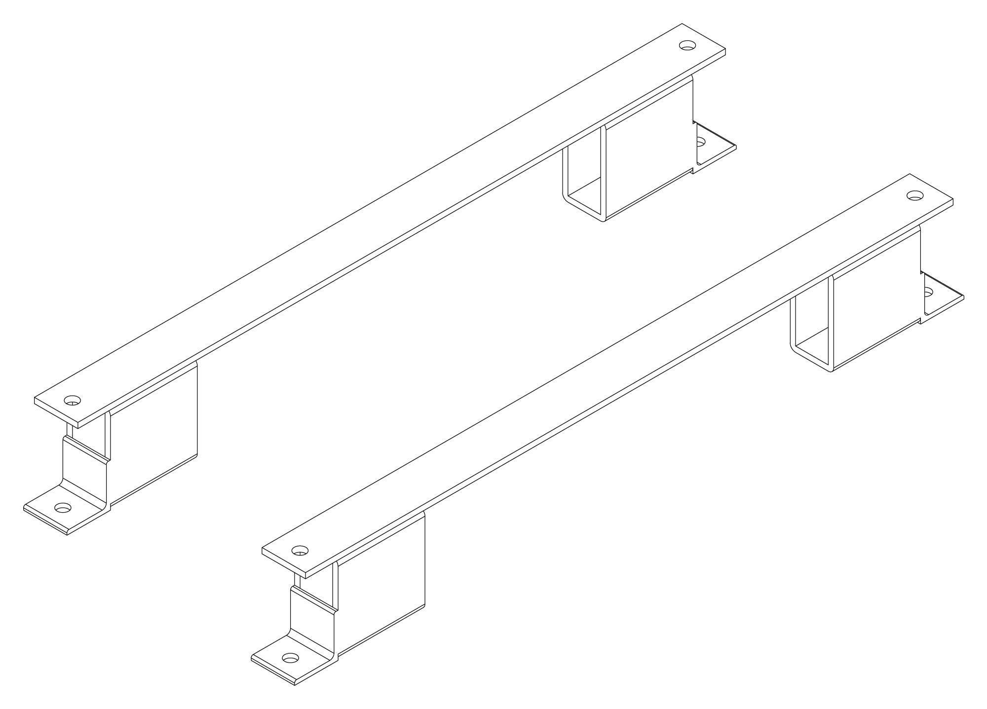
The following are vectorized diagrams for the ALx Series. Refer to the Downloads section for downloadable drawings.


Integrated Options
Standard integrated options are available for Magna-Power products, allowing the product's performance and communication interfaces to be tailors to the specific application.
- Option
- +CAN
- Option
- +ECAT
- Option
- +EIP
- Option
- +LXI

- Option
- +MTCP
Accessories
External accessories and integration services available for this product.