Serie ALx
DC Electronic Load
- Size
- 3U to 24U
- Power
- 1.25 kW to 20 kW
- Manufactured
- USA
- Build-time
- 6-8 weeks
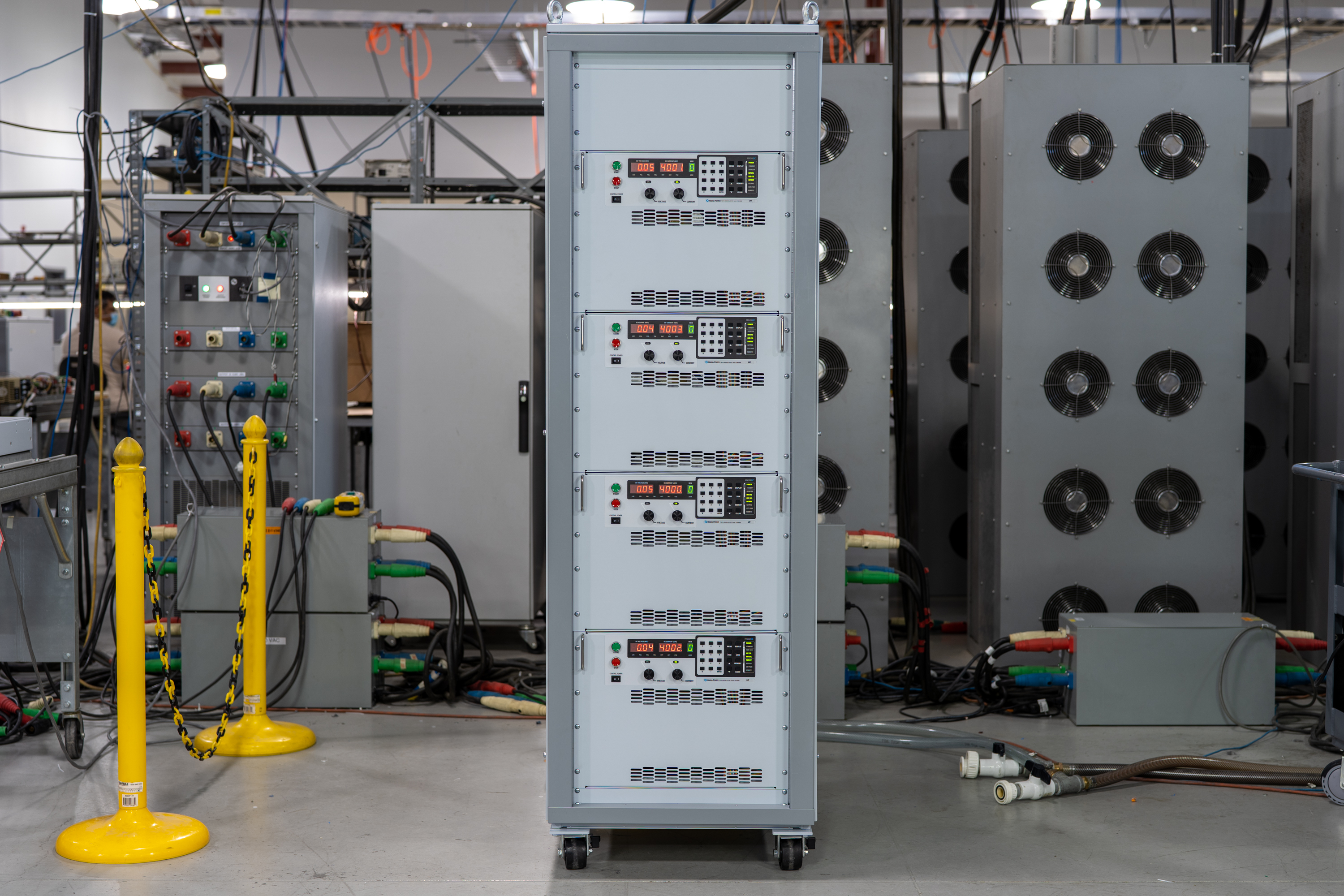
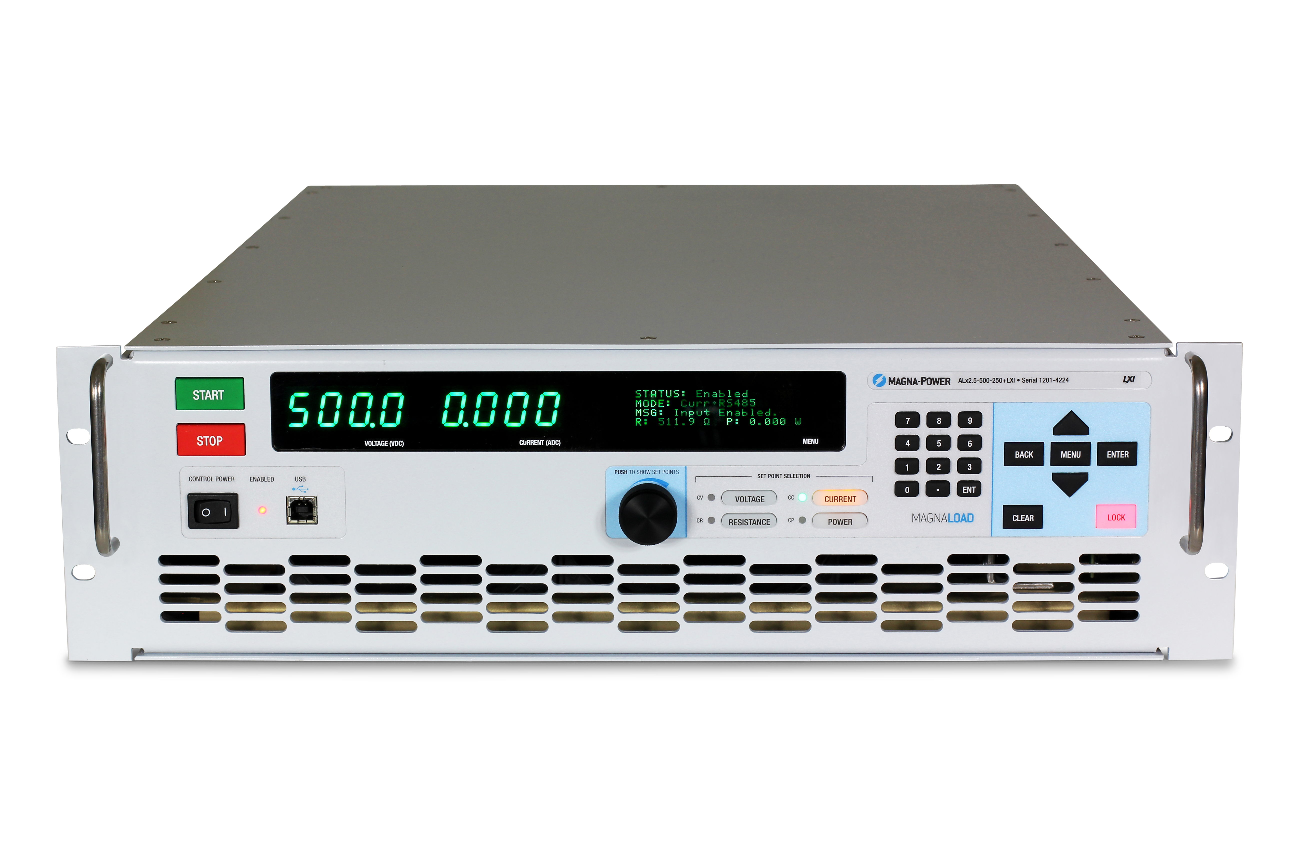
The ALx Series MagnaLOAD utilizes conventional linear MOSFET-based dissipative elements, allowing the series to achieve a very wide voltage-current operating range within the model’s maximum power rating. Using the same heat management innovations developed for Magna-Power’s high density programmable DC power supplies, the ALx Series’ conservative cooling ensures long product life with continuous full power operation in environments up to 50°C ambient operating temperature.

Talk with an expert
Do more with MagnaLINK™ distributed digital control.

Controllo e misura di precisione
Precisione guidata da DSP dal setpoint al punto di carico.
La Serie SLx è dotata della piattaforma di controllo digitale xGen MagnaLINK™ di Magna-Power, che utilizza una rete distribuita di DSP e comunicazioni scheda-scheda ad alta velocità basate su un protocollo di comunicazione a basso livello sviluppato internamente. La programmazione interna dei guadagni con guadagni regolabili in campo supporta un'ampia gamma di condizioni di carico.
- Controllo di tensione, corrente e potenza con risoluzione a 16 bit.
- Controlli programmabili della velocità di variazione (slew-rate).
- Stabilità nativa di 100 ppm.
- Rilevamento della tensione locale, remoto e senza cavi per una regolazione accurata al punto di carico.

Master-slaving plug-and-play
Scala la potenza senza interruzioni con valori di sistema aggregati.
Le doppie porte MagnaLINK offrono un master-slaving digitale-ibrido di nuova generazione, consentendo a un'unità di comandare uno stack sincronizzato. Espandi la capacità di corrente collegando in parallelo fino a 16 unità. Un collegamento secondario di rilevamento della corrente fornisce la corrente analogica in tempo reale al master per un'aggregazione e una visualizzazione accurate.
- Collegamento in parallelo di fino a 16 unità con semplice cablaggio dell'interfaccia.
- Un unico setpoint; uscita e protezioni sincronizzate.
- Feedback secondario di rilevamento della corrente per una condivisione accurata.
- Configurazione automatica e misurazioni aggregate su un unico display master.
From lab scripts to factory PLCs, flexible programming & integration.
Integrazione software semplificata
Comandi leggibili, risultati immediati: compatibile con qualsiasi linguaggio.
La Serie SLx offre un'API testuale chiara con supporto nativo SCPI e Modbus. Oltre 60 comandi ben documentati coprono avvio/arresto, set point per tensione, corrente e potenza, controllo dello slew rate, misurazioni ad alta precisione e configurazione completa, permettendo ai vostri script e sistemi di passare rapidamente dal proof-of-concept alla produzione.
- Set di comandi SCPI e Modbus con comportamento coerente.
- Avvio/arresto e protezioni: abilitazione uscita, impostazione limiti di intervento, interrogazione stato.
- Letture ad alta precisione: tensione, corrente, potenza e feedback di sense.
- Documentazione ed esempi orientati allo sviluppatore.
import serial
magnaPower = serial.Serial(port='COM4', baudrate=115200)
magnaPower.write('*IDN?\n'.encode())
print magna_power.readline()
magnaPower.write('VOLT 0\n'.encode())
magnaPower.write('CURR 0\n'.encode())
magnaPower.write('OUTP:START\n'.encode())
magnaPower.write('VOLT 270\n'.encode())
currSetPoints = [50, 100, 150, 250]
for currSetPoint in currSetPoints:
    print 'Setting Current to %s A' % currSetPoint
    magnaPower.write('CURR {0}\n'.format(currSetPoint).encode())
    magnaPower.write('MEAS:VOLT?\n'.encode())
    print magnaPower.readline()
    time.sleep(20)
magnaPower.write('OUTP:STOP\n'.encode())
magnaPower.close()
magna_power = serial('COM4', 'BaudRate', 115200);
fopen(magnaPower);
fprintf(magnaPower,'*IDN?');
idn = fscanf(magnaPower);
fprintf(magnaPower,'VOLT 0');
fprintf(magnaPower,'CURR 0');
fprintf(magnaPower,'OUTP:START');
fprintf(magnaPower,'VOLT 270');
for currSetPoint in [50, 100, 150, 250]
    display('Setting Current to '+currSetPoint+' A');
    fprintf(magnaPower, 'CURR '+currSetPoint);
    fprintf(magnaPower,'MEAS:VOLT?');
    display(fscanf(magnaPower));
    pause(20);
end
#include <stdio.h>
#include <stdint.h>
#include <string.h>
#include <windows.h>

int main()
{
    printf("Opening connection.\n");

    uint8_t recvBuffer[sizeof(uint8_t) * 256];
    memset(recvBuffer, 0, 256);

    // Choose the serial port name.
    // COM ports higher than COM9 need the \\.\ prefix, which is written as
    // "\\\\.\\" in C because we need to escape the backslashes.
    const char* device = "\\\\.\\COM4";

    // Choose the baud rate (bits per second).
    uint32_t baud_rate = 115200;

    HANDLE port = open_serial_port(device, baud_rate);
    if (port == INVALID_HANDLE_VALUE) { return 1; }

    char* scpiCmd = (char*)"*IDN?\n";
    size_t cmdLen = strlen(scpiCmd);
    int result = write_port(port, (uint8_t*)scpiCmd, cmdLen);
    if (result < 0)
        return -1;

    result = read_port(port, recvBuffer, 256);
    printf("Sent: %s\nReceived: %s\n", scpiCmd, recvBuffer);

    scpiCmd = (char*)"VOLT 0\n";
    cmdLen = strlen(scpiCmd);
    result = write_port(port, (uint8_t*)scpiCmd, cmdLen);
    if (result < 0)
        return -1;

    scpiCmd = (char*)"CURR 0\n";
    cmdLen = strlen(scpiCmd);
    result = write_port(port, (uint8_t*)scpiCmd, cmdLen);
    if (result < 0)
        return -1;

    scpiCmd = (char*)"OUTP:START\n";
    cmdLen = strlen(scpiCmd);
    result = write_port(port, (uint8_t*)scpiCmd, cmdLen);
    if (result < 0)
        return -1;

    scpiCmd = (char*)"VOLT 270\n";
    cmdLen = strlen(scpiCmd);
    result = write_port(port, (uint8_t*)scpiCmd, cmdLen);
    if (result < 0)
        return -1;

    char setPoints[4][5] = {"50", "100", "150", "200"};
    char setPointBuffer[40];
    scpiCmd = (char*)"MEAS:VOLT?\n";

    for (int i = 0; i < 4; i++)
    {
        sprintf(setPointBuffer, "CURR %s\n", setPoints[i]);
        printf("Setting current to %s A\n", setPoints[i]);
        cmdLen = strlen(setPointBuffer);
        result = write_port(port, (uint8_t*)setPointBuffer, cmdLen);
        if (result < 0)
            return -1;
        memset(recvBuffer, 0, 256);
        result = read_port(port, recvBuffer, 256);
        printf("Received: %s\n", recvBuffer);
        Sleep(20000);  // 20000ms = 20s
    }

    scpiCmd = (char*)"OUTP:STOP\n";
    cmdLen = strlen(scpiCmd);
    result = write_port(port, (uint8_t*)scpiCmd, cmdLen);
    if (result < 0)
        return -1;

    CloseHandle(port);

    printf("Connection closed.\n");
    return 0;
}
using System;
using System.IO.Ports;
using System.Threading;

namespace SerialCommunicationInCSharp
{
  public class Program
  {
    static bool _continue;
    static SerialPort serialPort;

    public static void Main(string[] args)
    {
      Thread readThread = new Thread(Read);

      Console.WriteLine("Opening connection.");

      // Create a new SerialPort object with default settings.
      serialPort = new SerialPort("COM4", 115200, Parity.None, 8, StopBits.One);

      // Set the read/write timeouts
      serialPort.ReadTimeout = 500;
      serialPort.WriteTimeout = 500;

      serialPort.Open();
      _continue = true;
      readThread.Start();

      Console.WriteLine("Sending: *IDN?");
      serialPort.WriteLine("*IDN?");

      serialPort.WriteLine("VOLT 0");
      serialPort.WriteLine("CURR 0");
      serialPort.WriteLine("OUTP:START");
      serialPort.WriteLine("VOLT 270");

      string[] currSetPoints = { "50", "100", "150", "250" };
ß
      for(int i = 0; i < currSetPoints.Length; i++)
      {
        serialPort.WriteLine(String.Format("'CURR {0}", currSetPoints[i]));
        serialPort.WriteLine("MEAS:VOLT?");
        Thread.Sleep(20000);
      }

      serialPort.WriteLine("OUTP:STOP");

      Console.WriteLine("Closing connection.");
      _continue = false;
      serialPort.Close();
      }

    public static void Read()
    {
      while (_continue)
      {
        try
        {
          string message = serialPort.ReadLine();
          Console.WriteLine("Received: " + message);
        }
        catch (TimeoutException) { }
      }
    }
  }
}

User I/O Esterno
Controlli analogico-digitali isolati e flessibili.
Tutti gli alimentatori della Serie SLx sono dotati di serie di un connettore D-Sub a 26 pin designato come User I/O Esterno. Questo connettore fornisce:
- 8 uscite digitali (logica 5V)
- 4 ingressi digitali (logica 5V)
- 4 uscite analogiche (logica 0-10V)
- 4 ingressi analogici (logica 0-10V)
L'User I/O Esterno è isolato dai terminali di uscita e riferito alla massa di terra. I pin del connettore sono configurabili dall'utente, consentendo di selezionare le funzioni necessarie per la propria applicazione e garantendo al contempo la possibilità di integrare nuove funzionalità in futuro. Le uscite digitali possono essere utilizzate per integrare l'alimentatore con, ad esempio, segnali di abilitazione esterni o logica di monitoraggio guasti digitale, oppure per monitorare tensione e corrente tramite le uscite analogiche 0-10V. È inoltre disponibile un ingresso analogico dedicato ad alta velocità, campionato a 2 kHz per un controllo pressoché in tempo reale.
Comunicazioni e controllo industriali
Dalle reti di laboratorio ai PLC: integrazione secondo le tue esigenze.
La Serie viene fornita pronta per il collegamento con doppia USB (frontale e posteriore) e RS485, con supporto per SCPI e Modbus. Per reti e automazione industriale, sono disponibili opzioni completamente integrate con supporto Modbus, documentazione completa e file di descrizione dispositivo per accelerare la configurazione del PLC e la mappatura dei tag.
- Doppia USB standard (frontale + posteriore) e RS485.
- Rete TCP/IP con opzione LXI TCP/IP Ethernet (+LXI)
- Opzioni fieldbus per PLC: CANopen (+CAN), EtherCAT (+ECAT), EtherNet/IP (+EIP), Modbus-TCP (+MTCP), PROFINET (+PROF).
- File dispositivo inclusi: EDS (CANopen/EtherNet/IP), ESI XML (EtherCAT), GSDML (PROFINET) per una rapida integrazione con il PLC.
- Documentazione completa dei comandi, esempi e diagnostica.
Software MagnaCTRL incluso
Dashboard multi-prodotto per controllo, diagnostica e aggiornamenti—pronti all'uso.
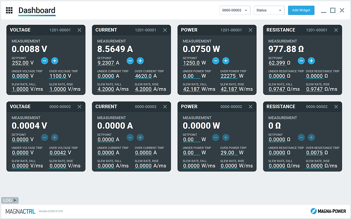
MagnaCTRL è una piattaforma di controllo multi-prodotto moderna, inclusa con i prodotti xGen. Crea dashboard, configura l'I/O, esegui aggiornamenti e accedi a diagnostiche approfondite—tutto da un'unica applicazione.
- Dashboard configurabile: aggiungi/organizza widget per monitorare e controllare più unità collegate.
- Product Explorer: rileva automaticamente i dispositivi, salva le connessioni e riconnettiti automaticamente nelle sessioni future.
- Pannello External User I/O: mappa l'I/O a 26 pin, esporta/importa le mappe dei pin per implementazioni rapide.
- Aggiornamenti firmware/software: rileva automaticamente le nuove versioni; esegui aggiornamenti manuali offline se necessario (vedi Changelog)
- Strumenti di calibrazione: regola guadagni/offset di programmazione/misurazione; con la guida, ottimizza i guadagni dell'anello di controllo.
- Registrazione dati: output grafico e registrazione .csv di tensione, corrente e misurazioni/impostazioni di potenza nel tempo
State-of-the-art USA manufacturing with worldwide support

Made in the USA
Produzione verticalmente integrata per un controllo qualità completo.
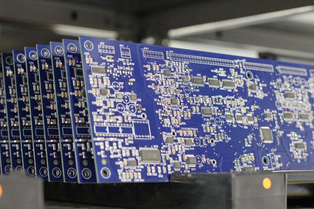
I prodotti Magna-Power sono progettati, costruiti, testati e assistiti presso la sede centrale di Magna-Power di 73.500 sq-ft a Flemington, New Jersey, dove lavorazioni metalliche, componenti magnetici, assemblaggio PCB e rodaggio vengono eseguiti internamente per un controllo rigoroso su qualità, costi e tempi di consegna.
- Prodotto negli USA: ingegneria, produzione e assistenza sotto un unico tetto.
- Produzione interna: lavorazioni metalliche, componenti magnetici, PCB SMT e finiture.
- Affidabilità comprovata: ogni unità completamente testata, calibrata e sottoposta a rodaggio.
Assistenza mondiale e supporto ricambi OEM
Competenza di fabbrica, risposta locale.
Magna-Power supporta i propri prodotti con centri di assistenza di fabbrica e autorizzati in Nord America, Europa, Regno Unito, Asia-Pacifico, Asia orientale e Sud America, utilizzando procedure di fabbrica e ricambi originali per ripristinare le unità alle specifiche originali, in garanzia e fuori garanzia.
- Copertura globale: sede centrale nel New Jersey e centri di assistenza autorizzati regionali.
- Riparazioni uniformi: diagnostica di fabbrica, istruzioni operative e schemi di sistema.
- Ricambi OEM originali: gruppi di ricambio testati per un servizio prevedibile e con tempi di fermo ridotti.
Model Ordering Guide
For both ordering and production, ALx Series models are uniquely defined by several key characteristics, as defined by the following diagram:

ALx Series Models
There are 27 different models in the ALx Series spanning power levels: 1.25 kW, 2.5 kW, 5 kW, 7.5 kW, 10 kW, 12.5 kW, 15 kW, 17.5 kW, 20 kW. To determine the appropriate model:
- Select the desired Max Voltage (Vdc) from the left-most column.
- Select the desired Max Current (Adc) from the same row that contains your desired Max Voltage.
- Construct your model number according to the model ordering guide.
| Model | Max Power kW |
Max Voltage Vdc |
Max Current Adc |
Package Type | Min Voltage Vdc |
Max Resistance Ω |
|---|---|---|---|---|---|---|
| ALx1.25-200-300 | 1.25 | 200 | 300 | Rack-mount | 2.5 | 70.40 |
| ALx1.25-500-125 | 1.25 | 500 | 125 | Rack-mount | 6.0 | 448.00 |
| ALx1.25-1000-37.5 | 1.25 | 1000 | 37.5 | Rack-mount | 7.5 | 1792.00 |
| ALx2.5-200-600 | 2.5 | 200 | 600 | Rack-mount | 2.5 | 70.40 |
| ALx2.5-500-250 | 2.5 | 500 | 250 | Rack-mount | 6.0 | 448.00 |
| ALx2.5-1000-75 | 2.5 | 1000 | 75 | Rack-mount | 7.5 | 1792.00 |
| ALx5-200-1200 | 5 | 200 | 1200 | Floor-standing | 2.5 | 35.20 |
| ALx5-500-500 | 5 | 500 | 500 | Floor-standing | 6.0 | 224.00 |
| ALx5-1000-150 | 5 | 1000 | 150 | Floor-standing | 7.5 | 896.00 |
| ALx7.5-200-1800 | 7.5 | 200 | 1800 | Floor-standing | 2.5 | 23.47 |
| ALx7.5-500-750 | 7.5 | 500 | 750 | Floor-standing | 6.0 | 149.33 |
| ALx7.5-1000-225 | 7.5 | 1000 | 225 | Floor-standing | 7.5 | 597.33 |
| ALx10-200-2400 | 10 | 200 | 2400 | Floor-standing | 2.5 | 17.60 |
| ALx10-500-1000 | 10 | 500 | 1000 | Floor-standing | 6.0 | 112.00 |
| ALx10-1000-300 | 10 | 1000 | 300 | Floor-standing | 7.5 | 448.00 |
| ALx12.5-200-3000 | 12.5 | 200 | 3000 | Floor-standing | 2.5 | 14.08 |
| ALx12.5-500-1250 | 12.5 | 500 | 1250 | Floor-standing | 6.0 | 89.60 |
| ALx12.5-1000-375 | 12.5 | 1000 | 375 | Floor-standing | 7.5 | 358.40 |
| ALx15-200-3600 | 15 | 200 | 3600 | Floor-standing | 2.5 | 11.73 |
| ALx15-500-1500 | 15 | 500 | 1500 | Floor-standing | 6.0 | 74.67 |
| ALx15-1000-450 | 15 | 1000 | 450 | Floor-standing | 7.5 | 298.67 |
| ALx17.5-200-4200 | 17.5 | 200 | 4200 | Floor-standing | 2.5 | 10.06 |
| ALx17.5-500-1750 | 17.5 | 500 | 1750 | Floor-standing | 6.0 | 64.00 |
| ALx17.5-1000-525 | 17.5 | 1000 | 525 | Floor-standing | 7.5 | 256.00 |
| ALx20-200-4800 | 20 | 200 | 4800 | Floor-standing | 2.5 | 8.80 |
| ALx20-500-2000 | 20 | 500 | 2000 | Floor-standing | 6.0 | 56.00 |
| ALx20-1000-600 | 20 | 1000 | 600 | Floor-standing | 7.5 | 224.00 |
Specifications are subject to change without notice. Unless otherwise noted, all specifications measured at the product's maximum ratings.
AC Input Specifications
200-240 Vac (UI2: Universal Input 2); Available on 20 kW Models
Programming Interface Specifications
USB Host (Rear): Type B
RS485 (Rear): RJ-45
MagnaLINK™: RJ-25 x 2
GPIB (Rear): IEEE-488
Referenced to Earth ground; isolated from the DC input
See User Manual for pin layout
Programming Specifications
Current: ±0.2% of full scale current rating
Power: ±0.3% of full scale power rating
Resistance: ±0.3% of full scale resistance rating
Current Mode: 2 ms, 10% to 90% full scale current rating
Power Mode: 100 ms, 10% to 90% full scale power rating
Resistance Mode: 200 ms, 10% to 90% full scale resistance rating
Under Voltage: 0% to 110% of full scale voltage rating
Over Current: 10% to 110% of full scale current rating
Over Power: 10% to 110% of full scale power rating
External User I/O Specifications
Digital Input Impedance: 10 kΩ
Digital Monitoring Voltage: 5V, 32 mA capacity
Digital Reference Voltage: 5V, 20 mA capacity
Analog Programming Voltage: 0-10 V
Analog Programming Resolution: 12-bit, 0.025%
Analog Monitoring Voltage: 0-10 V, 3 mA capacity
Analog Monitoring Impedance: 0.005 Ω
Analog Monitoring Accuracy: 0.05% of full scale
Analog Reference Voltage: 10 V, 20 mA capacity
Physical Specifications
5.25” H x 19” W x 24” D (13.34 x 48.26 x 60.96 cm)
40 lbs (18.1 kg)
5.25” H x 19” W x 24” D (13.34 x 48.26 x 60.96 cm)
65 lbs (29.5 kg)
30.7” H x 24” W x 31.5” D (78.0 x 61.0 x 80.0 cm)
255 lbs (115.7 kg)
30.7” H x 24” W x 31.5” D (78.0 x 61.0 x 80.0 cm)
320 lbs (145.2 kg)
30.7” H x 24” W x 31.5” D (78.0 x 61.0 x 80.0 cm)
385 lbs (174.6 kg)
58.25” H x 24” W x 31.5” D (148.0 x 61.0 x 80.0 cm)
500 lbs (226.8 kg)
58.25” H x 24” W x 31.5” D (148.0 x 61.0 x 80.0 cm)
565 lbs (256.3 kg)
58.25” H x 24” W x 31.5” D (148.0 x 61.0 x 80.0 cm)
630 lbs (285.8 kg)
58.25” H x 24” W x 31.5” D (148.0 x 61.0 x 80.0 cm)
695 lbs (315.3 kg)
Environmental Specifications
Regulatory Specifications
CISPR 22 / EN 55022 Class A
CSA C22.2 No. 61010-1:12; A1:2018
UL 61010-1:Ed.3,2012(R2019)
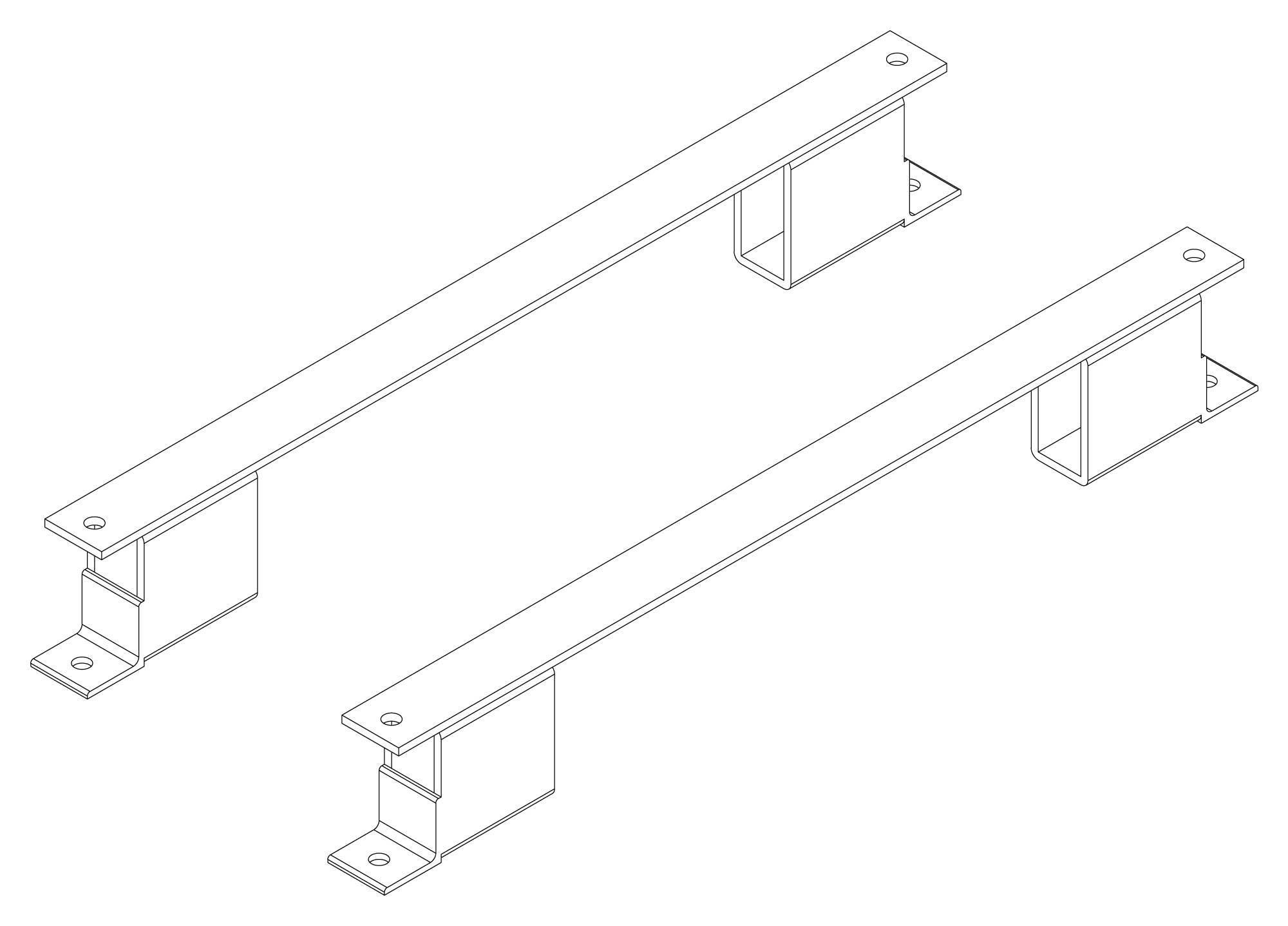
The following are vectorized diagrams for the ALx Series. Refer to the Downloads section for downloadable drawings.


Integrated Options
Standard integrated options are available for Magna-Power products, allowing the product's performance and communication interfaces to be tailors to the specific application.
- Option
- +CAN
- Option
- +ECAT
- Option
- +EIP
- Option
- +LXI

- Option
- +MTCP
Accessories
External accessories and integration services available for this product.