Série ALx
DC Electronic Load
- Size
- 3U to 24U
- Power
- 1.25 kW to 20 kW
- Manufactured
- USA
- Build-time
- 6-8 weeks
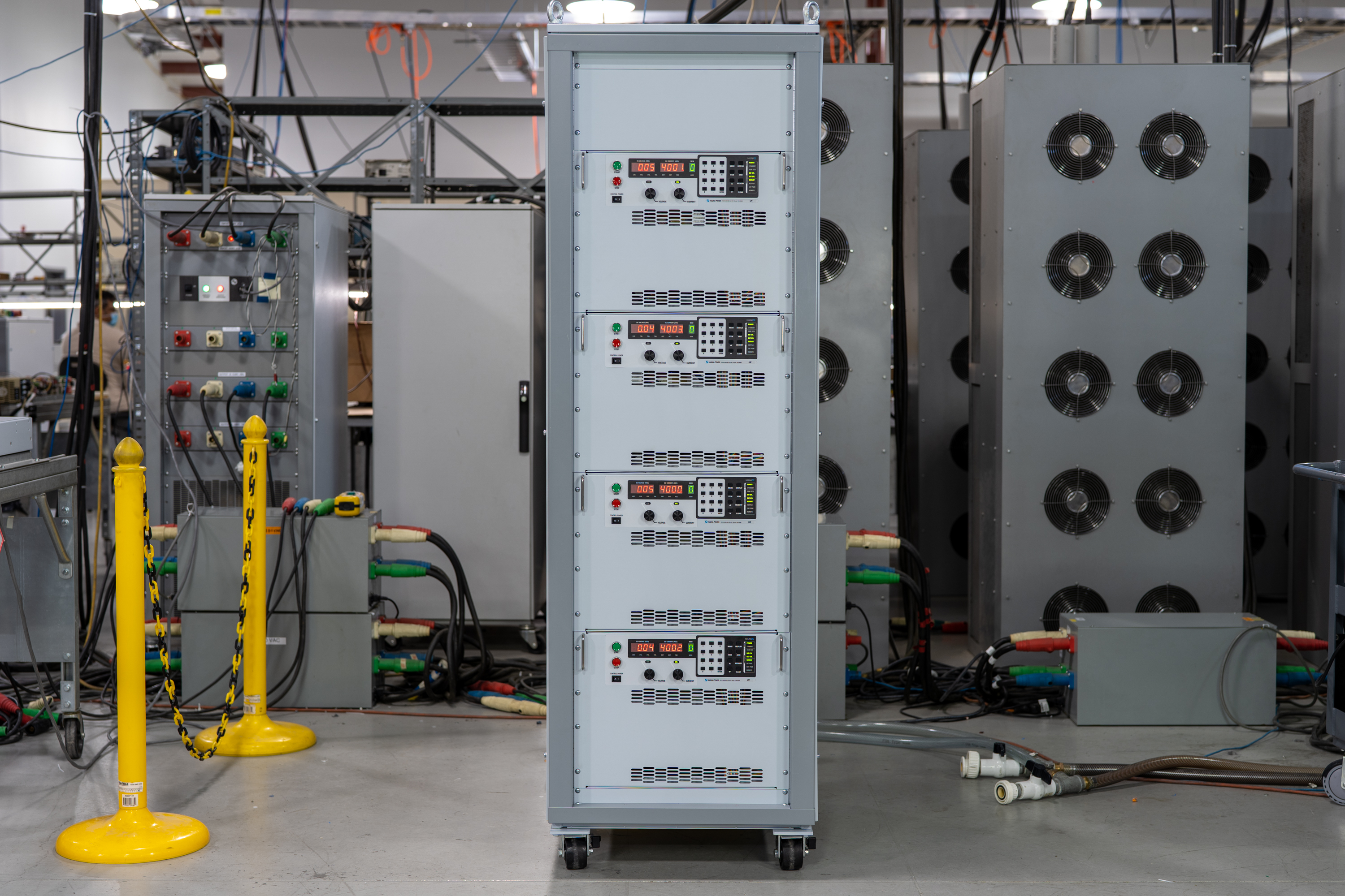
The ALx Series MagnaLOAD utilizes conventional linear MOSFET-based dissipative elements, allowing the series to achieve a very wide voltage-current operating range within the model’s maximum power rating. Using the same heat management innovations developed for Magna-Power’s high density programmable DC power supplies, the ALx Series’ conservative cooling ensures long product life with continuous full power operation in environments up to 50°C ambient operating temperature.

Talk with an expert
Do more with MagnaLINK™ distributed digital control.

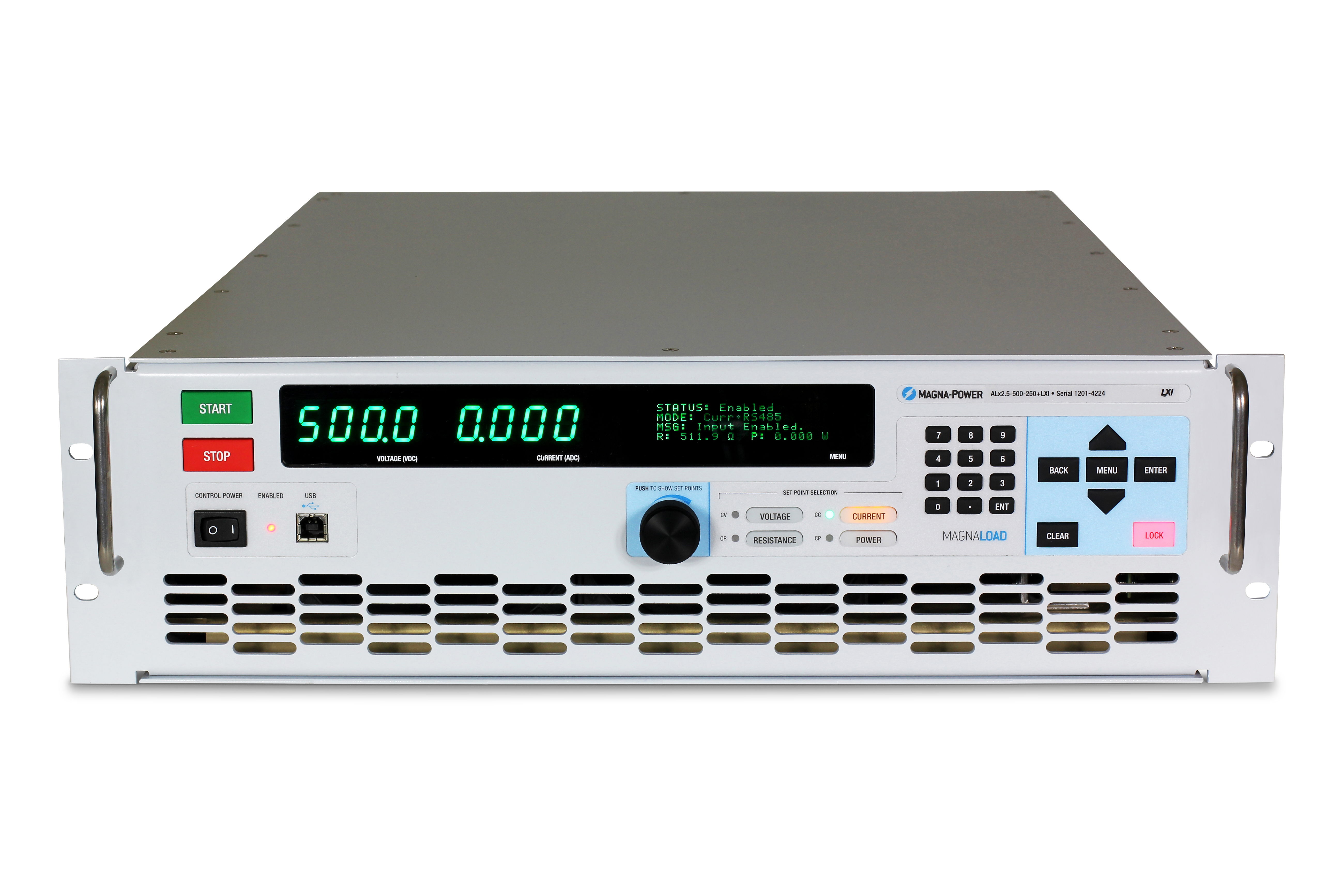
Contrôle et mesure de précision
Précision pilotée par DSP, du point de consigne au point de charge.
La série SLx est dotée de la plateforme de contrôle numérique xGen MagnaLINK™ de Magna-Power, qui utilise un réseau distribué de DSP et des communications carte-à-carte à haute vitesse exploitant un protocole de communication bas niveau développé en interne. La programmation interne des gains avec des gains ajustables sur le terrain prend en charge une large gamme de conditions de charge.
- Contrôle de la tension, du courant et de la puissance avec une résolution de 16 bits.
- Contrôles programmables de la vitesse de balayage.
- Stabilité native de 100 ppm.
- Détection de tension locale, à distance et sans fil pour une régulation précise au point de charge.

Maître-esclave plug-and-play
Augmentez la puissance de manière transparente avec des valeurs nominales de système agrégées.
Les deux ports MagnaLINK offrent une interconnexion maître-esclave hybride numérique de nouvelle génération, permettant à une seule unité de commander une pile synchronisée. Augmentez la capacité en courant en mettant jusqu'à 16 unités en parallèle. Une connexion secondaire de mesure de courant fournit le courant analogique en temps réel au maître pour une agrégation et un affichage précis.
- Mise en parallèle de jusqu'à 16 unités avec un câblage d'interface simple.
- Un seul point de consigne ; sortie et protections synchronisées.
- Retour de mesure de courant secondaire pour un partage précis.
- Auto-configuration et mesures agrégées sur un seul affichage maître.
From lab scripts to factory PLCs, flexible programming & integration.
Intégration logicielle simplifiée
Commandes lisibles, résultats rapides—compatible avec tout langage.
La série SLx offre une API textuelle claire avec SCPI natif et Modbus. Plus de 60 commandes bien documentées couvrent le démarrage/arrêt, les points de consigne pour la tension, le courant et la puissance, le contrôle de la vitesse de balayage, les mesures de haute précision et la configuration complète—pour que vos scripts et systèmes passent rapidement du prototype à la production.
- Jeux de commandes SCPI et Modbus avec un comportement cohérent.
- Démarrage/arrêt et protections : activation de la sortie, définition des seuils de déclenchement, interrogation de l'état.
- Lectures de haute précision : tension, courant, puissance et retour de mesure.
- Documentation et exemples orientés développeurs.
import serial
magnaPower = serial.Serial(port='COM4', baudrate=115200)
magnaPower.write('*IDN?\n'.encode())
print magna_power.readline()
magnaPower.write('VOLT 0\n'.encode())
magnaPower.write('CURR 0\n'.encode())
magnaPower.write('OUTP:START\n'.encode())
magnaPower.write('VOLT 270\n'.encode())
currSetPoints = [50, 100, 150, 250]
for currSetPoint in currSetPoints:
    print 'Setting Current to %s A' % currSetPoint
    magnaPower.write('CURR {0}\n'.format(currSetPoint).encode())
    magnaPower.write('MEAS:VOLT?\n'.encode())
    print magnaPower.readline()
    time.sleep(20)
magnaPower.write('OUTP:STOP\n'.encode())
magnaPower.close()
magna_power = serial('COM4', 'BaudRate', 115200);
fopen(magnaPower);
fprintf(magnaPower,'*IDN?');
idn = fscanf(magnaPower);
fprintf(magnaPower,'VOLT 0');
fprintf(magnaPower,'CURR 0');
fprintf(magnaPower,'OUTP:START');
fprintf(magnaPower,'VOLT 270');
for currSetPoint in [50, 100, 150, 250]
    display('Setting Current to '+currSetPoint+' A');
    fprintf(magnaPower, 'CURR '+currSetPoint);
    fprintf(magnaPower,'MEAS:VOLT?');
    display(fscanf(magnaPower));
    pause(20);
end
#include <stdio.h>
#include <stdint.h>
#include <string.h>
#include <windows.h>

int main()
{
    printf("Opening connection.\n");

    uint8_t recvBuffer[sizeof(uint8_t) * 256];
    memset(recvBuffer, 0, 256);

    // Choose the serial port name.
    // COM ports higher than COM9 need the \\.\ prefix, which is written as
    // "\\\\.\\" in C because we need to escape the backslashes.
    const char* device = "\\\\.\\COM4";

    // Choose the baud rate (bits per second).
    uint32_t baud_rate = 115200;

    HANDLE port = open_serial_port(device, baud_rate);
    if (port == INVALID_HANDLE_VALUE) { return 1; }

    char* scpiCmd = (char*)"*IDN?\n";
    size_t cmdLen = strlen(scpiCmd);
    int result = write_port(port, (uint8_t*)scpiCmd, cmdLen);
    if (result < 0)
        return -1;

    result = read_port(port, recvBuffer, 256);
    printf("Sent: %s\nReceived: %s\n", scpiCmd, recvBuffer);

    scpiCmd = (char*)"VOLT 0\n";
    cmdLen = strlen(scpiCmd);
    result = write_port(port, (uint8_t*)scpiCmd, cmdLen);
    if (result < 0)
        return -1;

    scpiCmd = (char*)"CURR 0\n";
    cmdLen = strlen(scpiCmd);
    result = write_port(port, (uint8_t*)scpiCmd, cmdLen);
    if (result < 0)
        return -1;

    scpiCmd = (char*)"OUTP:START\n";
    cmdLen = strlen(scpiCmd);
    result = write_port(port, (uint8_t*)scpiCmd, cmdLen);
    if (result < 0)
        return -1;

    scpiCmd = (char*)"VOLT 270\n";
    cmdLen = strlen(scpiCmd);
    result = write_port(port, (uint8_t*)scpiCmd, cmdLen);
    if (result < 0)
        return -1;

    char setPoints[4][5] = {"50", "100", "150", "200"};
    char setPointBuffer[40];
    scpiCmd = (char*)"MEAS:VOLT?\n";

    for (int i = 0; i < 4; i++)
    {
        sprintf(setPointBuffer, "CURR %s\n", setPoints[i]);
        printf("Setting current to %s A\n", setPoints[i]);
        cmdLen = strlen(setPointBuffer);
        result = write_port(port, (uint8_t*)setPointBuffer, cmdLen);
        if (result < 0)
            return -1;
        memset(recvBuffer, 0, 256);
        result = read_port(port, recvBuffer, 256);
        printf("Received: %s\n", recvBuffer);
        Sleep(20000);  // 20000ms = 20s
    }

    scpiCmd = (char*)"OUTP:STOP\n";
    cmdLen = strlen(scpiCmd);
    result = write_port(port, (uint8_t*)scpiCmd, cmdLen);
    if (result < 0)
        return -1;

    CloseHandle(port);

    printf("Connection closed.\n");
    return 0;
}
using System;
using System.IO.Ports;
using System.Threading;

namespace SerialCommunicationInCSharp
{
  public class Program
  {
    static bool _continue;
    static SerialPort serialPort;

    public static void Main(string[] args)
    {
      Thread readThread = new Thread(Read);

      Console.WriteLine("Opening connection.");

      // Create a new SerialPort object with default settings.
      serialPort = new SerialPort("COM4", 115200, Parity.None, 8, StopBits.One);

      // Set the read/write timeouts
      serialPort.ReadTimeout = 500;
      serialPort.WriteTimeout = 500;

      serialPort.Open();
      _continue = true;
      readThread.Start();

      Console.WriteLine("Sending: *IDN?");
      serialPort.WriteLine("*IDN?");

      serialPort.WriteLine("VOLT 0");
      serialPort.WriteLine("CURR 0");
      serialPort.WriteLine("OUTP:START");
      serialPort.WriteLine("VOLT 270");

      string[] currSetPoints = { "50", "100", "150", "250" };
ß
      for(int i = 0; i < currSetPoints.Length; i++)
      {
        serialPort.WriteLine(String.Format("'CURR {0}", currSetPoints[i]));
        serialPort.WriteLine("MEAS:VOLT?");
        Thread.Sleep(20000);
      }

      serialPort.WriteLine("OUTP:STOP");

      Console.WriteLine("Closing connection.");
      _continue = false;
      serialPort.Close();
      }

    public static void Read()
    {
      while (_continue)
      {
        try
        {
          string message = serialPort.ReadLine();
          Console.WriteLine("Received: " + message);
        }
        catch (TimeoutException) { }
      }
    }
  }
}

User I/O externe
Commandes analogiques-numériques isolées et flexibles.
Toutes les alimentations de la série SLx sont équipées en standard d'un connecteur D-Sub 26 broches désigné comme User I/O externe. Ce connecteur fournit :
- 8 sorties numériques (logique 5V)
- 4 entrées numériques (logique 5V)
- 4 sorties analogiques (logique 0-10V)
- 4 entrées analogiques (logique 0-10V)
Le User I/O externe est isolé des bornes de sortie et référencé à la terre. Les broches du connecteur sont configurables par l'utilisateur, permettant de sélectionner les fonctions nécessaires à leur application, tout en offrant une capacité d'évolution pour de nouvelles fonctionnalités. Utilisez les sorties numériques pour intégrer l'alimentation avec, par exemple, des signaux d'activation externes ou une logique de surveillance numérique des défauts, ou surveillez la tension et le courant à l'aide des sorties analogiques 0-10V. Une entrée analogique haute vitesse dédiée est également fournie, échantillonnée à 2 kHz pour un contrôle en temps quasi réel.
Communications et contrôle industriels
Du réseau de laboratoire aux automates—intégrez selon vos besoins.
La série est livrée prête à connecter avec double USB (avant et arrière) et RS485, avec prise en charge de SCPI et Modbus. Pour les réseaux et l'automatisation industrielle, choisissez des options entièrement intégrées avec prise en charge Modbus, une documentation complète—et des fichiers de description d'appareil pour accélérer la configuration des automates et le mappage des variables.
- Double USB standard (avant + arrière) et RS485.
- Réseau TCP/IP avec l'option LXI TCP/IP Ethernet (+LXI)
- Options de bus de terrain pour automates : CANopen (+CAN), EtherCAT (+ECAT), EtherNet/IP (+EIP), Modbus-TCP (+MTCP), PROFINET (+PROF).
- Fichiers de description inclus : EDS (CANopen/EtherNet/IP), ESI XML (EtherCAT), GSDML (PROFINET) pour une intégration rapide aux automates.
- Documentation complète des commandes, exemples et diagnostics.
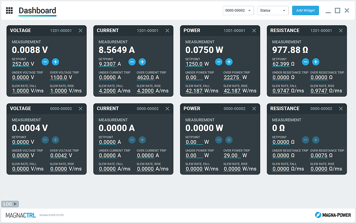
Logiciel MagnaCTRL inclus
Tableau de bord multi-produits pour le contrôle, les diagnostics et les mises à jour — prêt à l'emploi.
MagnaCTRL est une plateforme de contrôle multi-produits moderne, incluse avec les produits xGen. Créez des tableaux de bord, configurez les E/S, effectuez des mises à jour et accédez à des diagnostics approfondis — le tout depuis une seule application.
- Tableau de bord configurable : ajoutez/organisez des widgets pour surveiller et contrôler plusieurs unités connectées.
- Explorateur de produits : détection automatique des appareils, sauvegarde des connexions et reconnexion automatique lors des sessions futures.
- Panneau E/S utilisateur externe : mappez les E/S du connecteur 26 broches, exportez/importez les configurations de broches pour des déploiements rapides.
- Mises à jour du micrologiciel/logiciel : détection automatique des nouvelles versions ; mises à jour manuelles hors ligne si nécessaire (voir le journal des modifications)
- Outils de calibration : ajustez les gains/décalages de programmation/mesure ; avec les instructions, réglez les gains de la boucle de contrôle.
- Enregistrement des données : sortie graphique et journalisation .csv de la tension, du courant et des mesures et réglages de puissance au fil du temps
State-of-the-art USA manufacturing with worldwide support

Made in the USA
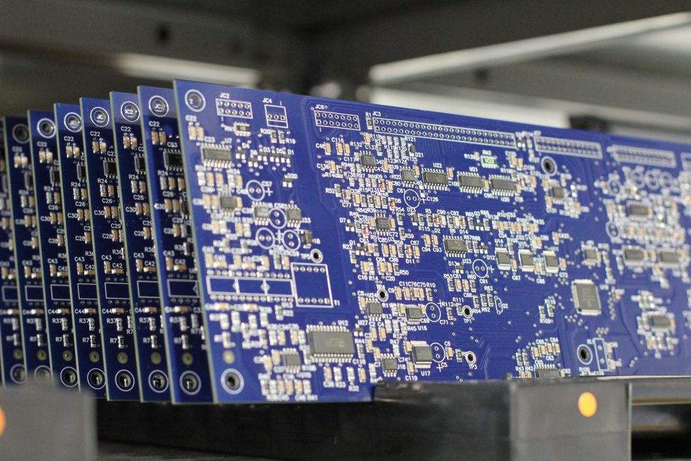
Fabrication verticalement intégrée pour un contrôle qualité total.
Les produits Magna-Power sont conçus, fabriqués, testés et entretenus au siège de Magna-Power, d'une superficie de 73 500 sq-ft à Flemington, New Jersey, où la métallurgie, les composants magnétiques, l'assemblage des PCB et le rodage sont tous réalisés en interne pour un contrôle rigoureux de la qualité, des coûts et des délais.
- Fabriqué aux USA : Ingénierie, fabrication et service sous un même toit.
- Production en interne : Métallurgie, composants magnétiques, PCB SMT et finitions.
- Fiabilité éprouvée : Chaque unité est entièrement testée, calibrée et rodée.
Service mondial et support de pièces OEM
Expertise d'usine, réponse locale.
Magna-Power garantit ses produits grâce à des centres de service agréés en usine à travers l'Amérique du Nord, l'Europe, le Royaume-Uni, l'Asie-Pacifique, l'Asie de l'Est et l'Amérique du Sud — utilisant des procédures d'usine et des pièces d'origine pour remettre les unités aux spécifications d'origine, sous garantie ou hors garantie.
- Couverture mondiale : siège social dans le New Jersey et centres de service agréés régionaux.
- Réparations homogènes : diagnostics d'usine, instructions de travail et schémas système.
- Pièces OEM d'origine : assemblages de remplacement testés pour un service prévisible et à faible temps d'arrêt.
Model Ordering Guide
For both ordering and production, ALx Series models are uniquely defined by several key characteristics, as defined by the following diagram:

ALx Series Models
There are 27 different models in the ALx Series spanning power levels: 1.25 kW, 2.5 kW, 5 kW, 7.5 kW, 10 kW, 12.5 kW, 15 kW, 17.5 kW, 20 kW. To determine the appropriate model:
- Select the desired Max Voltage (Vdc) from the left-most column.
- Select the desired Max Current (Adc) from the same row that contains your desired Max Voltage.
- Construct your model number according to the model ordering guide.
| Model | Max Power kW |
Max Voltage Vdc |
Max Current Adc |
Package Type | Min Voltage Vdc |
Max Resistance Ω |
|---|---|---|---|---|---|---|
| ALx1.25-200-300 | 1.25 | 200 | 300 | Rack-mount | 2.5 | 70.40 |
| ALx1.25-500-125 | 1.25 | 500 | 125 | Rack-mount | 6.0 | 448.00 |
| ALx1.25-1000-37.5 | 1.25 | 1000 | 37.5 | Rack-mount | 7.5 | 1792.00 |
| ALx2.5-200-600 | 2.5 | 200 | 600 | Rack-mount | 2.5 | 70.40 |
| ALx2.5-500-250 | 2.5 | 500 | 250 | Rack-mount | 6.0 | 448.00 |
| ALx2.5-1000-75 | 2.5 | 1000 | 75 | Rack-mount | 7.5 | 1792.00 |
| ALx5-200-1200 | 5 | 200 | 1200 | Floor-standing | 2.5 | 35.20 |
| ALx5-500-500 | 5 | 500 | 500 | Floor-standing | 6.0 | 224.00 |
| ALx5-1000-150 | 5 | 1000 | 150 | Floor-standing | 7.5 | 896.00 |
| ALx7.5-200-1800 | 7.5 | 200 | 1800 | Floor-standing | 2.5 | 23.47 |
| ALx7.5-500-750 | 7.5 | 500 | 750 | Floor-standing | 6.0 | 149.33 |
| ALx7.5-1000-225 | 7.5 | 1000 | 225 | Floor-standing | 7.5 | 597.33 |
| ALx10-200-2400 | 10 | 200 | 2400 | Floor-standing | 2.5 | 17.60 |
| ALx10-500-1000 | 10 | 500 | 1000 | Floor-standing | 6.0 | 112.00 |
| ALx10-1000-300 | 10 | 1000 | 300 | Floor-standing | 7.5 | 448.00 |
| ALx12.5-200-3000 | 12.5 | 200 | 3000 | Floor-standing | 2.5 | 14.08 |
| ALx12.5-500-1250 | 12.5 | 500 | 1250 | Floor-standing | 6.0 | 89.60 |
| ALx12.5-1000-375 | 12.5 | 1000 | 375 | Floor-standing | 7.5 | 358.40 |
| ALx15-200-3600 | 15 | 200 | 3600 | Floor-standing | 2.5 | 11.73 |
| ALx15-500-1500 | 15 | 500 | 1500 | Floor-standing | 6.0 | 74.67 |
| ALx15-1000-450 | 15 | 1000 | 450 | Floor-standing | 7.5 | 298.67 |
| ALx17.5-200-4200 | 17.5 | 200 | 4200 | Floor-standing | 2.5 | 10.06 |
| ALx17.5-500-1750 | 17.5 | 500 | 1750 | Floor-standing | 6.0 | 64.00 |
| ALx17.5-1000-525 | 17.5 | 1000 | 525 | Floor-standing | 7.5 | 256.00 |
| ALx20-200-4800 | 20 | 200 | 4800 | Floor-standing | 2.5 | 8.80 |
| ALx20-500-2000 | 20 | 500 | 2000 | Floor-standing | 6.0 | 56.00 |
| ALx20-1000-600 | 20 | 1000 | 600 | Floor-standing | 7.5 | 224.00 |
Specifications are subject to change without notice. Unless otherwise noted, all specifications measured at the product's maximum ratings.
AC Input Specifications
200-240 Vac (UI2: Universal Input 2); Available on 20 kW Models
Programming Interface Specifications
USB Host (Rear): Type B
RS485 (Rear): RJ-45
MagnaLINK™: RJ-25 x 2
GPIB (Rear): IEEE-488
Referenced to Earth ground; isolated from the DC input
See User Manual for pin layout
Programming Specifications
Current: ±0.2% of full scale current rating
Power: ±0.3% of full scale power rating
Resistance: ±0.3% of full scale resistance rating
Current Mode: 2 ms, 10% to 90% full scale current rating
Power Mode: 100 ms, 10% to 90% full scale power rating
Resistance Mode: 200 ms, 10% to 90% full scale resistance rating
Under Voltage: 0% to 110% of full scale voltage rating
Over Current: 10% to 110% of full scale current rating
Over Power: 10% to 110% of full scale power rating
External User I/O Specifications
Digital Input Impedance: 10 kΩ
Digital Monitoring Voltage: 5V, 32 mA capacity
Digital Reference Voltage: 5V, 20 mA capacity
Analog Programming Voltage: 0-10 V
Analog Programming Resolution: 12-bit, 0.025%
Analog Monitoring Voltage: 0-10 V, 3 mA capacity
Analog Monitoring Impedance: 0.005 Ω
Analog Monitoring Accuracy: 0.05% of full scale
Analog Reference Voltage: 10 V, 20 mA capacity
Physical Specifications
5.25” H x 19” W x 24” D (13.34 x 48.26 x 60.96 cm)
40 lbs (18.1 kg)
5.25” H x 19” W x 24” D (13.34 x 48.26 x 60.96 cm)
65 lbs (29.5 kg)
30.7” H x 24” W x 31.5” D (78.0 x 61.0 x 80.0 cm)
255 lbs (115.7 kg)
30.7” H x 24” W x 31.5” D (78.0 x 61.0 x 80.0 cm)
320 lbs (145.2 kg)
30.7” H x 24” W x 31.5” D (78.0 x 61.0 x 80.0 cm)
385 lbs (174.6 kg)
58.25” H x 24” W x 31.5” D (148.0 x 61.0 x 80.0 cm)
500 lbs (226.8 kg)
58.25” H x 24” W x 31.5” D (148.0 x 61.0 x 80.0 cm)
565 lbs (256.3 kg)
58.25” H x 24” W x 31.5” D (148.0 x 61.0 x 80.0 cm)
630 lbs (285.8 kg)
58.25” H x 24” W x 31.5” D (148.0 x 61.0 x 80.0 cm)
695 lbs (315.3 kg)
Environmental Specifications
Regulatory Specifications
CISPR 22 / EN 55022 Class A
CSA C22.2 No. 61010-1:12; A1:2018
UL 61010-1:Ed.3,2012(R2019)
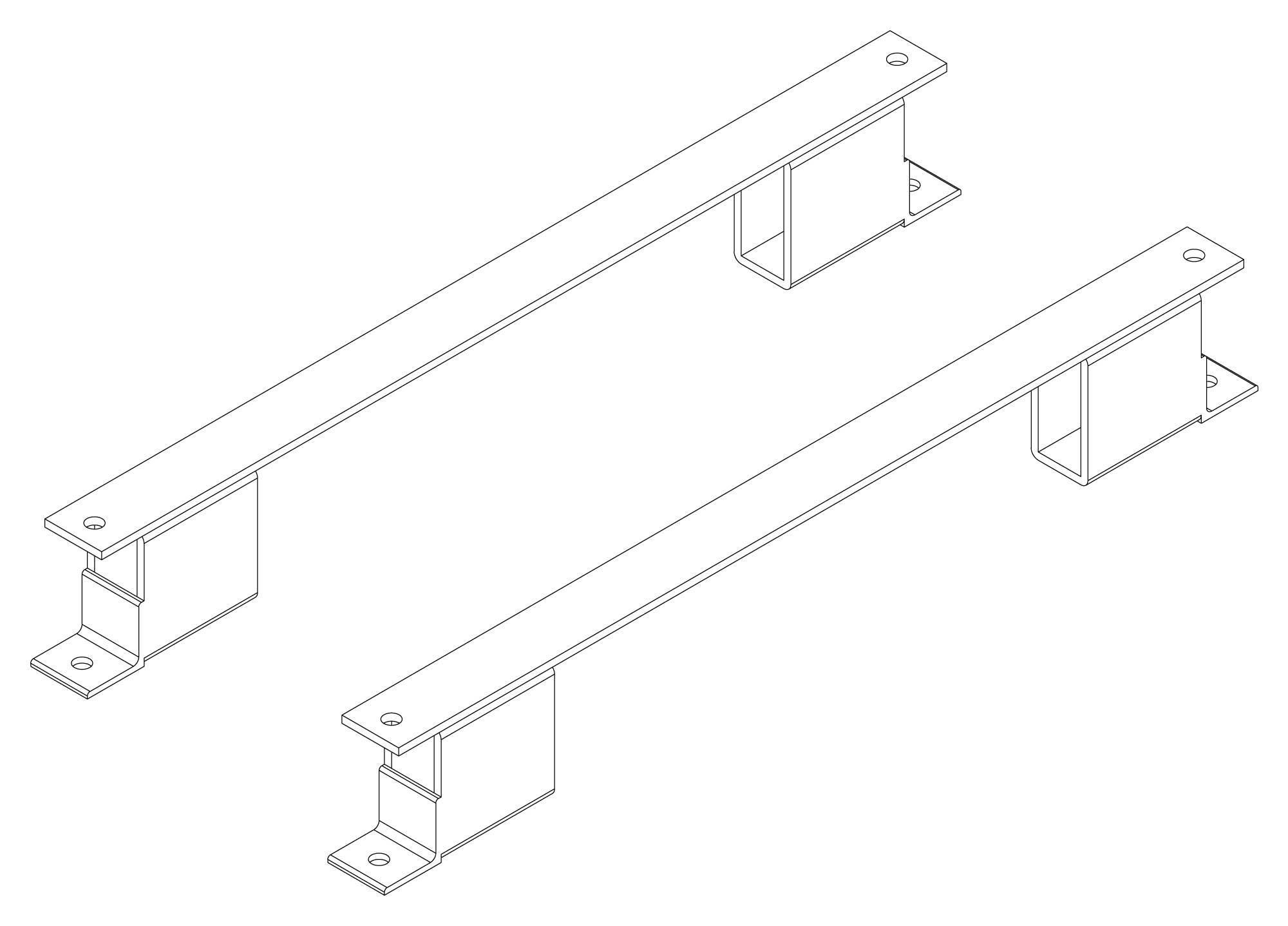
The following are vectorized diagrams for the ALx Series. Refer to the Downloads section for downloadable drawings.


Integrated Options
Standard integrated options are available for Magna-Power products, allowing the product's performance and communication interfaces to be tailors to the specific application.
- Option
- +CAN
- Option
- +ECAT
- Option
- +EIP
- Option
- +LXI

- Option
- +MTCP
Accessories
External accessories and integration services available for this product.