
Série TS
Programmable DC Power Supply
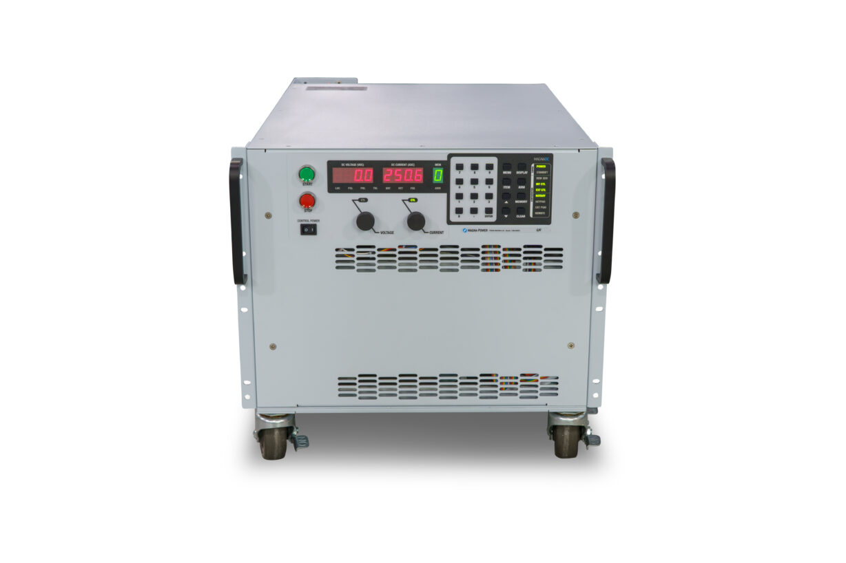
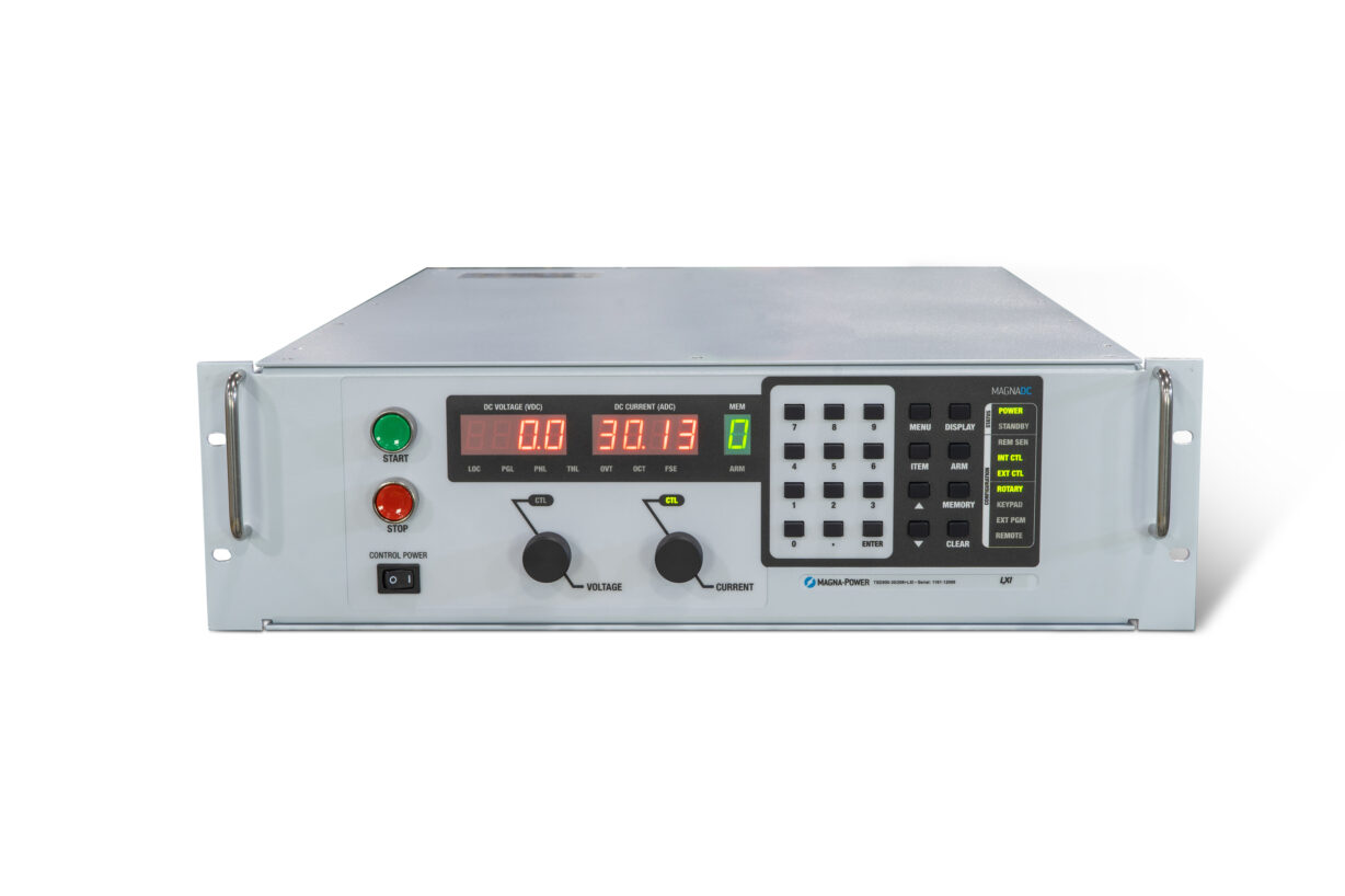
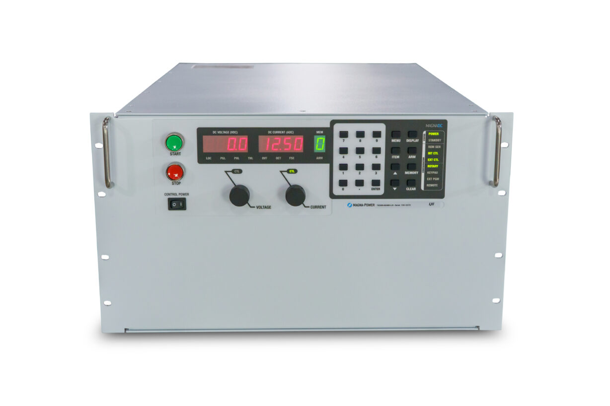
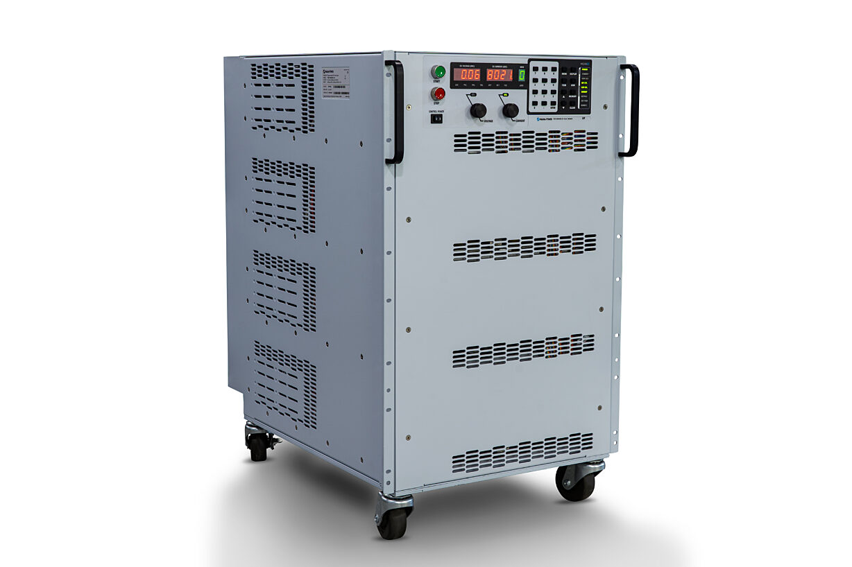
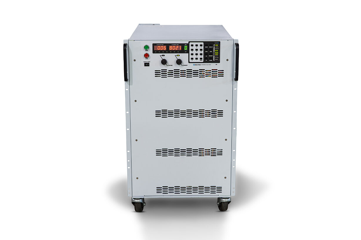
The TS Series offers many models spanning a wide voltage and current range, while still maintaining among the highest power density rack-mount packaging. The TS Series covers voltages from 5 Vdc up to 6000 Vdc (floating) and current levels from 1.2 Adc up to 8000 Adc. Models 5 kW to 15 kW are available in a 3U chassis, models 20 kW and 25 kW are available in a 4U chassis, models 30 kW are available in a 6U chassis, models 40 kW and 50 kW are available in an 8U chassis with removable casters, models 75 kW models are available in a 12U chassis with removable casters, and 100 kW models are available in a 16U chassis with removable casters. In addition, there are several special low voltage high current models, enabling a more cost-effective solution for these requirements. All TS Series power supplies come standard with isolated 37-pin external I/O, RS232, Remote Interface Software, IVI drivers, and LabVIEW drivers for integration into a variety of programming environment.
Build-Time: 10-14 Weeks







Current-Fed Topology: Robust Power Conversion
All MagnaDC programmable DC power supplies utilize high-frequency IGBT-based power processing in current-fed topology. This topology adds an additional stage over the conventional voltage-fed topology for enhanced control and system protection, ensuring that even under a fault condition, the power supply will self-protect. Due to the self-protecting characteristics of this topology, the possibility of fast rising current spikes and magnetic core saturation is eliminated.


Made in the USA, Available Worldwide
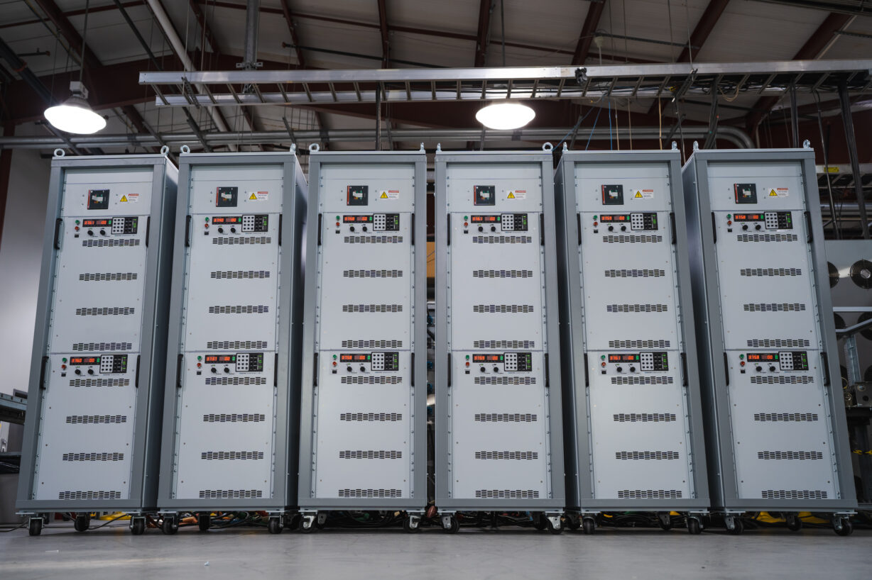
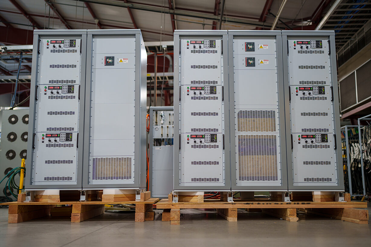
For complete control of quality, MagnaDC programmable DC power supplies are designed and manufactured at Magna-Power's vertically integrated USA manufacturing facility in Flemington, New Jersey. Heat-sinks and various metal assemblies are machined from aluminum. Sheet metal is cut, punched, sanded, bent, and powder coated in-house. Magnetics are wound-to-order from validated designs based on a model's voltage and current. A full surface mount technology (SMT) with multiple stages of 3D automated optical inspection ensure high-quality board assemblies. Finally after assembly, products undergo comprehensive test and calibration, followed by an extended burn-in period.
Standard Safety Features
MagnaDC programmable DC power supplies have extensive diagnostic functions, including:
- AC Phase Loss
- Excessive Thermal Conditions
- Over Voltage Trip (Programmable)
- Over Current Trip (Programmable)
- Cleared Fuse
- Excessive Program Line Voltage
- Interlock Fault
When in standby or diagnostic fault, the AC mains are mechanically disconnected by an embedded AC contactor, providing confidence that the unit is only processing power when desired.
Finally, with a dedicated +5V interlock input pin and included +5V reference on all models, external emergency stop systems can be easily integrated using an external contact.
Limitless Programming Capabilities
With support for Standard Commands for Programmable Instrumentation (SCPI), MagnaDC power supplies provide an easy to use API with ASCII commands in readable text. Over 40 commands allow programmatic access to product registers, starting and stopping the product, control of voltage and current, high-accuracy measurement queries, and product configuration. Simple scripting or complex software can be achieved, with extensive documentation and examples provided by Magna-Power.
MagnaDC power supplies include RS232 communication interface standard with optional LXI TCP/IP Ethernet (+LXI) and IEEE-488 GPIB (+GPIB) options.

External User I/O for Analog and PLC Control
Using the standard rear isolated 37-pin user I/O connector, the MagnaDC programmable power supplies can be completely controlled and monitored using external signals. The voltage, current, over voltage and over current set points can be set by applying a 0-10V analog signal. Remote start, stop, clear and interlock (emergency stop tie-in) are controlled by applying a 5V digital signal. Each diagnostic condition is given a designated pin, which reads +5V when high. Reference +5V and +10V signals are provided, eliminating the need for external voltage signals and allowing the use of dry contacts.
All communications and user I/IO pins are isolated from the output terminals and referenced to earth-ground as standard.
High Performance Master-Slave Operation
All MagnaDC programmable DC power supplies come with master-slaving capability.
The MagnaDC master-slaving strategy helps to ensures no degradation in performance as units are added in parallel or series by providing gate drive signals directly from the master to the slave units. This strategy ensures one control loop for the system and eliminates the noise susceptibility commonly found when sending analog control references over long distances.
The Universal Interface Device 47 (UID47) accessory eases master-slave parallel or series configuration of Magna-Power DC power supplies, enabling near equal current or voltage sharing, depending on the configuration.
Master-slave series operation is supported to combined voltages up to the product's DC Output Isolation specification. No external blocking diodes are requires for series operation.
Magna-Power Software, NI LabVIEW Drivers, and IVI Drivers
All MagnaDC power supplies come standard with an IVI driver and an NI LabVIEW driver featuring a full set of VIs. Get started quickly with either driver using included example programs.
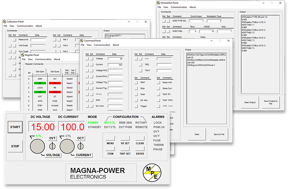
Magna-Power's included Remote Interface Software (pictured) provides an easy and intuitive method to operate a Magna-Power Electronics power supply with computer control. The software includes a virtual control panel, command panel to explore available commands, register panel to monitor the power supply status, calibration panel for recalibrating internal digital potentiometers, firmware panel for upgrading firmware, and a finally a modulation panel to emulate non-linear profiles.
All communication interfaces are supported across the various methods to program MagnaDC power supplies.
Front Panel - Standard

Front Panel - C Version

REM SEN: Remote sense enabled
INT CTL: Front panel start/stop/clear enabled
EXT CTL: External start/stop/clear enabled
ROTARY: Front panel rotary knob input
EXT PGM: External analog voltage-current control
REMOTE: Computer control
LOC: Interlock
PGL: External input voltage beyond limits
PHL: Under-voltage AC input
THL: Over-temperature condition
OVT: Over-voltage protection has tripped
OCT: Over-current protection has tripped
MENU: Selects function
ITEM: Selects item within function
V/I DIS: Displays voltage-current settings
TRIP DIS: Displays OVT and OCT setting
CLEAR: Clears settings or resets fault
ENTER: Select item
Model Ordering Guide
For both ordering and production, TS Series models are uniquely defined by several key characteristics, as defined by the following diagram:

TS Series Models
There are 275 different models in the TS Series spanning power levels: 5 kW, 10 kW, 15 kW, 20 kW, 25 kW, 30 kW, 40 kW, 50 kW, 75 kW, 100 kW. To determine the appropriate model:
- Select the desired Max Voltage (Vdc) from the left-most column.
- Select the desired Max Current (Adc) from the same row that contains your desired Max Voltage.
- Construct your model number according to the model ordering guide.
| 5 kW | 10 kW | 15 kW | 20 kW | 25 kW | 30 kW | 40 kW | 50 kW | 75 kW | 100 kW | |||
|---|---|---|---|---|---|---|---|---|---|---|---|---|
| 3U | 3U | 3U | 4U/6U** | 4U/6U** | 6U | 8U | 8U | 12U | 16U | |||
| Voltage Maximum (Vdc) | Current Maximum (Adc) | Ripple (mVrms) | Efficiency | |||||||||
| 5 | 900 | 1800* | 2700* | N/A | N/A | N/A | N/A | N/A | N/A | N/A | 50 | 84% |
| 8 | 600 | N/A | N/A | N/A | N/A | N/A | N/A | N/A | N/A | N/A | 40 | 85% |
| 10 | 500 | 900 | N/A | 2000*** | 2700* | N/A | 4000 | N/A | 6000 | 8000 | 40 | 87% |
| 16 | 300 | 600 | 900 | N/A | N/A | 1800 | N/A | N/A | N/A | N/A | 35 | 87% |
| 20 | 250 | 500 | 750 | 1000 | 1250 | 1500 | 2000 | 2500 | 3750 | 5000 | 40 | 88% |
| 25 | 200 | 400 | 600 | 800 | 1000 | 1200 | 1600 | 2000 | 3000 | 4000 | 40 | 89% |
| 32 | 150 | 300 | 450 | 625 | 781 | 900 | 1250 | 1562 | 2343 | 3124 | 40 | 89% |
| 40 | 125 | 250 | 375 | 500 | 625 | 750 | 1000 | 1250 | 1875 | 2500 | 40 | 89% |
| 50 | 100 | 200 | 300 | 400 | 500 | 600 | 800 | 1000 | 1500 | 2000 | 50 | 89% |
| 60 | 83 | 166 | 249 | 333 | 416 | 498 | 666 | 832 | 1248 | 1664 | 60 | 87% |
| 80 | 62 | 124 | 186 | 250 | 312.5 | 372 | 500 | 625 | 973.5 | 1250 | 60 | 90% |
| 100 | 50 | 100 | 150 | 200 | 250 | 300 | 400 | 500 | 750 | 1000 | 60 | 90% |
| 125 | 40 | 80 | 120 | 160 | 200 | 240 | 320 | 400 | 600 | 800 | 100 | 90% |
| 160 | 31 | 62 | 93 | 125 | 156 | 186 | 250 | 312 | 468 | 624 | 120 | 90% |
| 200 | 25 | 50 | 75 | 100 | 125 | 150 | 200 | 250 | 375 | 500 | 125 | 91% |
| 250 | 20 | 40 | 60 | 80 | 100 | 120 | 160 | 200 | 300 | 400 | 130 | 91% |
| 300 | 16 | 32 | 48 | 66.6 | 83.3 | 96 | 133.2 | 166.6 | 249.9 | 333.2 | 160 | 91% |
| 375 | 13 | 26 | 39 | 53.3 | 66.6 | 78 | 106.6 | 133.2 | 199.8 | 266.4 | 170 | 92% |
| 400 | 12 | 24 | 36 | 50 | 62.4 | 72 | 100 | 125 | 187.2 | 249.6 | 180 | 92% |
| 500 | 10 | 20 | 30 | 40 | 50 | 60 | 80 | 100 | 150 | 200 | 220 | 92% |
| 600 | 8 | 16 | 24 | 33.3 | 41.6 | 48 | 66.6 | 83.2 | 124.8 | 166.4 | 250 | 92% |
| 800 | 6 | 12 | 18 | 25 | 31.2 | 36 | 50 | 62.4 | 93.6 | 124.8 | 300 | 92% |
| 1000 | 5 | 10 | 15 | 20 | 25 | 30 | 40 | 50 | 75 | 100 | 350 | 92% |
| 1250 | 4 | 8 | 12 | 16 | 20 | 24 | 32 | 40 | 60 | 80 | 375 | 92% |
| 1500 | 3.3 | 6.6 | 9.9 | 13.3 | 16.6 | 19.8 | 26.6 | 33.2 | 49.8 | 66.4 | 400 | 92% |
| 2000 | 2.5 | 5 | 7.5 | 10 | 12.5 | 15 | 20 | 25 | 37.5 | 50 | 450 | 92% |
| 3000 | 1.6 | 3.2 | 4.8 | 6.6 | 8.3 | 9.6 | 13.2 | 16.6 | 24.9 | 33.2 | 500 | 92% |
| 4000 | 1.2 | 2.4 | 3.6 | 5 | 6.2 | 7.2 | 10 | 12.4 | 18.6 | 24.8 | 550 | 92% |
| 5000 | 1 | 2 | 3 | 4 | 5 | 6 | 8 | 10 | 15 | 20 | 1500 | 92% |
| 6000 | 0.8 | 1.6 | 2.5 | 3.3 | 4.1 | 5 | 6.6 | 8.3 | 12.3 | 16.4 | 1700 | 92% |
| AC Input Voltage (Vac) | Input Current Per Phase (Aac) | |||||||||||
| 208/240 Vac, 1Φ | 41 | N/A | N/A | N/A | N/A | N/A | N/A | N/A | N/A | N/A | ||
| 208/240 Vac, 3Φ | 18 | 36 | 52 | 69 | 85 | 105 | N/A | N/A | N/A | N/A | ||
| 380/415 Vac, 3Φ | 10 | 20 | 29 | 38 | 47 | 57 | 76 | 94 | 141 | 188 | ||
| 440/480 Vac, 3Φ | 9 | 17 | 25 | 33 | 40 | 50 | 66 | 82 | 120 | 160 | ||
* Models marked with an asterisk are special low-voltage high-current models that may vary in size and input current from the standard TS Series models within the same power envelope.
** 20/25 kW models with 380/415, 3Φ input or 440/480 Vac, 3Φ input come in a 4U chassis. 20/25 kW models with 208/240, 3Φ input come in a 6U chassis.
*** Available with 380/415, 3Φ input or 440/480 Vac, 3Φ input only.
Specifications
The following specifications are subject to change without notice. Unless otherwise noted, all specifications measured at the product's maximum ratings.
| Specification | Value |
|---|---|
1Φ AC Input Voltage
1Φ, 2-wire + ground; Available on 5 kW models only |
208 Vac (operating range 187 - 229 Vac) 240 Vac (operating range 216 - 264 Vac) |
3Φ AC Input Voltage
3Φ, 3-wire + ground |
208 Vac (operating range 187 to 229 Vac) 240 Vac (operating range 216 to 264 Vac) 380/400 Vac (operating range 342 to 440 Vac) 415 Vac (operating range 373 to 456 Vac) 440 Vac (operating range 396 to 484 Vac) 480 Vac (operating range 432 to 528 Vac) |
Input Frequency
|
50 Hz to 400 Hz |
Power Factor
|
> 0.92 at maximum power (3Φ Input) > 0.70 at maximum power (1Φ Input) |
AC Input Isolation
|
±2500 Vdc, maximum input voltage to ground |
| Specification | Value |
|---|---|
Voltage Ripple
|
Model specific. Refer to chart of available models. |
Line Regulation
Line regulation is a measure of a power supply's ability to maintain its output voltage (or current) given changes in the input line voltage. Line regulation is expressed as percent of change in the output voltage (or current) relative to the change in the input line voltage.
|
Voltage mode: ± 0.004% of full scale Current mode: ± 0.02% of full scale |
Load Regulation
Load regulation is a measure of the power supply's ability to maintain its output voltage (or current) given changes in the load, measured while operating at the maximum rated voltage (or current). Load regulation is expressed as the difference between voltage (or current) at full load minus voltage (or current) at min load, divided by the products max voltage (or current) rating.
|
Voltage mode: ± 0.01% of full scale Current mode: ± 0.04% of full scale |
Stability
|
± 0.10% for 8 hrs. after 30 min. warm-up |
Efficiency
|
85% to 95% Model specific. Refer to chart of available models. |
Maximum Slew Rate
Standard Models |
< 170 ms for a programmed output voltage change from 0 to 63% < 200 ms for a programmed output current change from 0 to 63% |
Maximum Slew Rate
Models with High Slew Rate Output (+HS) Option |
< 5 ms for a programmed output voltage change from 0 to 63% < 10 ms for a programmed output current change from 0 to 63% |
Bandwidth
Standard Models |
3 Hz with remote analog voltage programming 2 Hz with remote analog current programming |
Bandwidth
Models with High Slew Rate Output (+HS) Option |
60 Hz with remote analog voltage programming 45 Hz with remote analog current programming |
DC Output Isolation
Models Rated ≤1000 Vdc |
±1000 Vdc, maximum output voltage to ground |
DC Output Isolation
Models Rated >1000 Vdc or Models with +ISO Option |
±(3000 Vdc + Vo/2), maximum output voltage to ground where Vo is the maximum output voltage of the power supply |
| Specification | Value |
|---|---|
Front Panel Programming
|
Stepless aluminum rotary knobs and keypad |
Computer Interface
|
RS232, D-sub DB-9, female (Standard) LXI TCP/IP Ethernet RJ45 (Option +LXI) IEEE-488 GPIB (Option +GPIB) |
External User I/O Port
Analog and Digital Programming |
37-pin D-sub DB-37, female Referenced to Earth ground; isolated from power supply output See User Manual for pin layout |
Remote Sense Limits (Wired)
Available for models ≤ 1000 Vdc without High Isolation Output (+ISO) option |
3% maximum voltage drop from output to load |
| Specification | Value |
|---|---|
Voltage Programming Accuracy
Programming accuracy is a measure of how close the actual power supply output will be to the programmed setting, as measured by an ideal meter.
|
± 0.075% of max rated voltage |
Over Voltage Trip Programming Accuracy
|
± 0.075% of max rated voltage |
Current Programming Accuracy
Programming accuracy is a measure of how close the actual power supply output will be to the programmed setting, as measured by an ideal meter.
|
± 0.075% of max rated current |
Over Current Trip Programming Accuracy
|
± 0.075% of max rated current |
Voltage Readback Accuracy
Readback accuracy is a measure of how close the measured and displayed value will be to the actual power supply output.
|
± 0.2% of max rated voltage |
Current Readback Accuracy
Readback accuracy is a measure of how close the measured and displayed value will be to the actual power supply output.
|
± 0.2% of max rated current |
| Specification | Value |
|---|---|
Analog Programming and Monitoring Levels
|
0-10 Vdc |
Analog Output Impedances
|
Voltage output monitoring: 100 Ω Current output monitoring: 100 Ω +10V reference: 1 Ω |
Digital Programming and Monitoring Limits
|
Input: 0 to 5 Vdc, 10 kΩ input impedance Output: 0 to 5 Vdc, 5 mA drive capacity |
| Specification | Value |
|---|---|
Racking Standard
|
EIA-310 |
Rear Support Rails
|
Included |
Size and Weight
5 kW Models |
3U 5.25" H x 19" W x 24" D (13.34 x 48.26 x 60.96 cm) 74 lbs (34.57 kg) |
Size and Weight
10 kW Models |
3U 5.25" H x 19" W x 24" D (13.34 x 48.26 x 60.96 cm) 94 lbs (42.64 kg) |
Size and Weight
15 kW Models |
3U 5.25" H x 19" W x 24" D (13.34 x 48.26 x 60.96 cm) 125 lbs (56.70 kg) |
Size and Weight
20 kW Models; 380/415 Vac and 440/480 Vac, 3Φ input |
4U 7” H x 19” W x 24” D (17.8 x 48.2 x 60.9 cm) 160 lbs (72.6 kg) |
Size and Weight
20 kW Models; 208/240 Vac, 3Φ input |
6U 10.5" H x 19" W x 24" D (26.67 x 48.26 x 60.96 cm) 185 lbs (83.9 kg) |
Size and Weight
25 kW Models; 380/415 Vac and 440/480 Vac, 3Φ input |
4U 7” H x 19” W x 24” D (17.8 x 60.9 x 48.2 cm) 180 lbs (81.7 kg) |
Size and Weight
25 kW Models; 208/240 Vac, 3Φ input |
6U 10.5" H x 19" W x 24" D (26.67 x 48.26 x 60.96 cm) 220 lbs (99.79 kg) |
Size and Weight
30 kW Models |
6U 10.5" H x 19" W x 24" D (26.67 x 48.26 x 60.96 cm) 245 lbs (111.13 kg) |
Size and Weight
40 kW Models |
With casters removed: 8U 14” H x 19” W x 24” D (35.6 x 48.2 x 60.9 cm) 315 lbs (142.9 kg) With casters attached: 17.75” H x 19” W x 24” D (45.1 x 48.2 x 60.9 cm) 315 lbs (142.9 kg) |
Size and Weight
50 kW Models |
With casters removed: 8U 14” H x 19” W x 24” D (35.6 x 48.2 x 60.9 cm) 355 lbs (161.0 kg) With casters attached: 17.75” H x 19” W x 24” D (45.1 x 48.2 x 60.9 cm) 355 lbs (161.0 kg) |
Size and Weight
75 kW Models |
With casters removed: 12U 21” H x 19” W x 24” D (53.3 x 48.2 x 60.9 cm) 540 lbs (244.9 kg) With casters attached: 24.75” H x 19” W x 24” D (62.9 x 48.2 x 60.9 cm) 540 lbs (244.9 kg) |
Size and Weight
100 kW Models |
With casters removed: 16U 28” H x 19” W x 24” D (71.1 x 48.2 x 60.9 cm) 725 lbs (328.9 kg) With casters attached: 31.75” H x 19” W x 24” D (80.7 x 48.2 x 60.9 cm) 725 lbs (328.9 kg) |
| Specification | Value |
|---|---|
Ambient Operating Temperature
|
-25°C to 50°C |
Storage Temperature
|
-25°C to +85°C |
Humidity
|
Relative humidity up to 95% non-condensing |
Temperature Coefficient
|
0.04%/°C of maximum output voltage 0.06%/°C of maximum output current |
Air Cooling
3U and 6U Models |
Side air inlet, rear exhaust |
Air Cooling
4U, 8U, 12U, and 18U Models |
Front and side air inlet, rear exhaust |
Water Cooling
With Water Cooling (+WC) Option |
25°C maximum inlet temperature 1.5 GPM minimum flow rate for 3U/4U units 3.0 GPM minimum flow rate for 6U/8U units 4.5 GPM minimum flow rate for 12U units 6.0 GPM minimum flow rate for 16U units 80 PSI maximum pressure 1/4” NPT male pipe size (3U/4U models) 1/2” NPT male pipe size (6U/8U/12U/16U models) Front air intake, rear exhaust (6U/8U/12U/16U models only) |
| Specification | Value |
|---|---|
EMC
|
Complies with 2014/30/EU (EMC Directive) CISPR 22 / EN 55022 Class A |
Safety
|
Complies with EN61010-1 and 2014/35/EU (Low Voltage Directive) |
CE Mark
|
Yes |
RoHS Compliant
|
Yes |
Dimensional Diagrams
The following are vectorized diagrams for the TS Series. Refer to the Downloads section for downloadable drawings.
Options and Accessories
The following are options and accessories developed specifically for Magna-Power's TS Series
Accessories
External accessories and integration services are available for Magna-Power products
BDx Module
1U blocking diode module covering a wide range of voltages and currents and providing necessary cooling, power supply controls interface, and remote sensing location.
Cabinet and Integration
Various size cabinets, including 12U, 24U, 30U, 36U, 30Ux2 and 36Ux2, with casters, fans and product integration.
DBx Module
High-performance add-on bringing ultra-high stability less than 10 ppm, up to 24-bit resolution, and up to 10x reduction in ripple.
DC Power Cables
DC power cables with wide range voltage ratings, current ratings, and termination options, made-to-order by Magna-Power
UID47: Universal Interface Device 47
Master-slave interface device for load sharing. Includes interface device and (2) D-Sub 37-pin cables with a braided shield.
Additional Accessories
RS485 Converter
Industrial RS232 to Addressable RS485 Converter. Plugs into product's RS232 port.
UID46: Universal Interface Device 46
Master-slave interface device for load sharing. Includes interface device and (2) D-Sub 37 cables.
USB Edgeport Converter
Industrial Plug and Play USB to RS232 Converter. Adapter plugs into product's RS232 port.
Integrated Options
Standard integrated options are available for Magna-Power products, allowing the product's performance and communication interfaces to be tailors to the specific application.
High Isolation Output
Option Code: +ISO
Availability:
Available for models rated for 250 Vdc to 1000 Vdc, the +ISO option greatly increases the output isolation, used when the application demands floating or tying units in series beyond the standard ±1000 Vdc output isolation rating.
High Slew Rate Output
Option Code: +HS
Availability:
A hardware and control modification that replaces the standard output stage with one of low capacitance film and/or high RMS current rated aluminum electrolytic capacitors. This option provides higher bandwidth with faster output rise and fall times.
IEEE-488 GPIB
Option Code: +GPIB
Availability:
IEEE-488 General Purpose Interface Bus (GPIB) communication interface providing full command support and compatibility with other GPIB devices
Integrated Blocking Diode
Option Code: +BD
Availability:
An internally heatsinked protection diode on the positive output terminal of a MagnaDC programmable DC power supply to protect the product's output from reverse voltages far exceeding the product's output voltage rating.
LXI TCP/IP Ethernet
Option Code: +LXI
Availability:
TCP/IP Ethernet communication protocol and single RJ-45 interface, certified to the LXI Class C standard, for socket communications using conventional computer networks
Water Cooling
Option Code: +WC
Availability:
Using an integrated central heat exchanger and specially wound magnetic components, water cooling is available for select Magna-Power power supplies for use in densely packaged system cabinets, where heat removal by the product's standard air cooling presents a challenge.
Downloads
The following downloads are for the Série TS:


