Série SL
Programmable DC Power Supply
- Size
- 1U
- Power
- 1.5 kW to 10 kW
- Manufactured
- USA
- Build-time
- 4-6 weeks
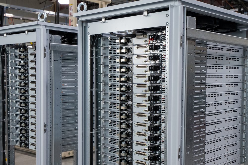
The SL Series builds on over 40 years of power supply innovation at Magna-Power, designed from the ground up to meet the highly reliable power dense demands of ATE system integrators through Magna-Power's signature current-fed power processing topology. Utilizing state-of-the-art semiconductors and innovative internally designed and manufactured heat sinks, the SL Series offers industry-leading 1U (1.75” height) programmable power levels with models at 1.5 kW, 2.6 kW, 4 kW, 6 kW, 8 kW, and 10 kW while still maintaining an ambient operating temperature rating up to 50°C.

Talk with an expert


Fast, accurate power delivery with controls and options tailored to your needs
Puissance et performance 1U inégalées
Sortie propre et précise avec une réponse rapide pour les systèmes exigeants.
Les alimentations de la série SL offrent une réponse transitoire rapide, une programmation et une mesure de haute précision, une résolution de 12 bits et une faible ondulation de sortie—le tout dans un boîtier 1U de référence avec un rendement allant jusqu'à 95 %. Avec un fonctionnement en tension constante ou en courant constant et un basculement automatique, elles se stabilisent rapidement après les échelons de charge (récupération de transitoire de charge de l'ordre de quelques millisecondes) et maintiennent vos consignes avec précision, avec une exactitude de programmation en tension et en courant allant jusqu'à ±0,075 % de la pleine échelle—idéales pour les applications de test de précision, de rodage et de procédés industriels où la dynamique et la précision sont essentielles.
Configuré sur commande avec options intégrées
Fonctionnalités standard riches, extensibles selon les besoins.
SL Series starts with a strong base: SCPI over RS232, isolated 37-pin user I/O, LabVIEW and IVI drivers, and Remote Interface Software included. When applications demand more, fully integrated options tailor performance, connectivity, and mechanics—without external boxes or ad-hoc wiring.
Standard SCPI computer controls, RS232, isolated 37-pin analog/digital I/O, LabVIEW & IVI drivers, RIS software.
-
High Slew Rate Output (+HS) for higher bandwidth and faster programmed rise times.
-
Connectivity options LXI TCP/IP Ethernet (+LXI) and IEEE-488 GPIB (+GPIB).
-
Ruggedized (+RUG) for MIL-STD shock & vibration
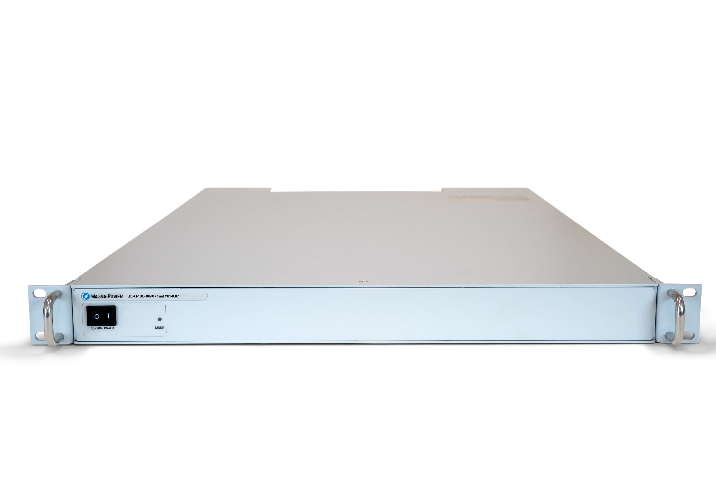
Commande en façade sans palier avec option de panneau vierge
Accessible là où vous en avez besoin, dissimulé là où vous n'en avez pas.
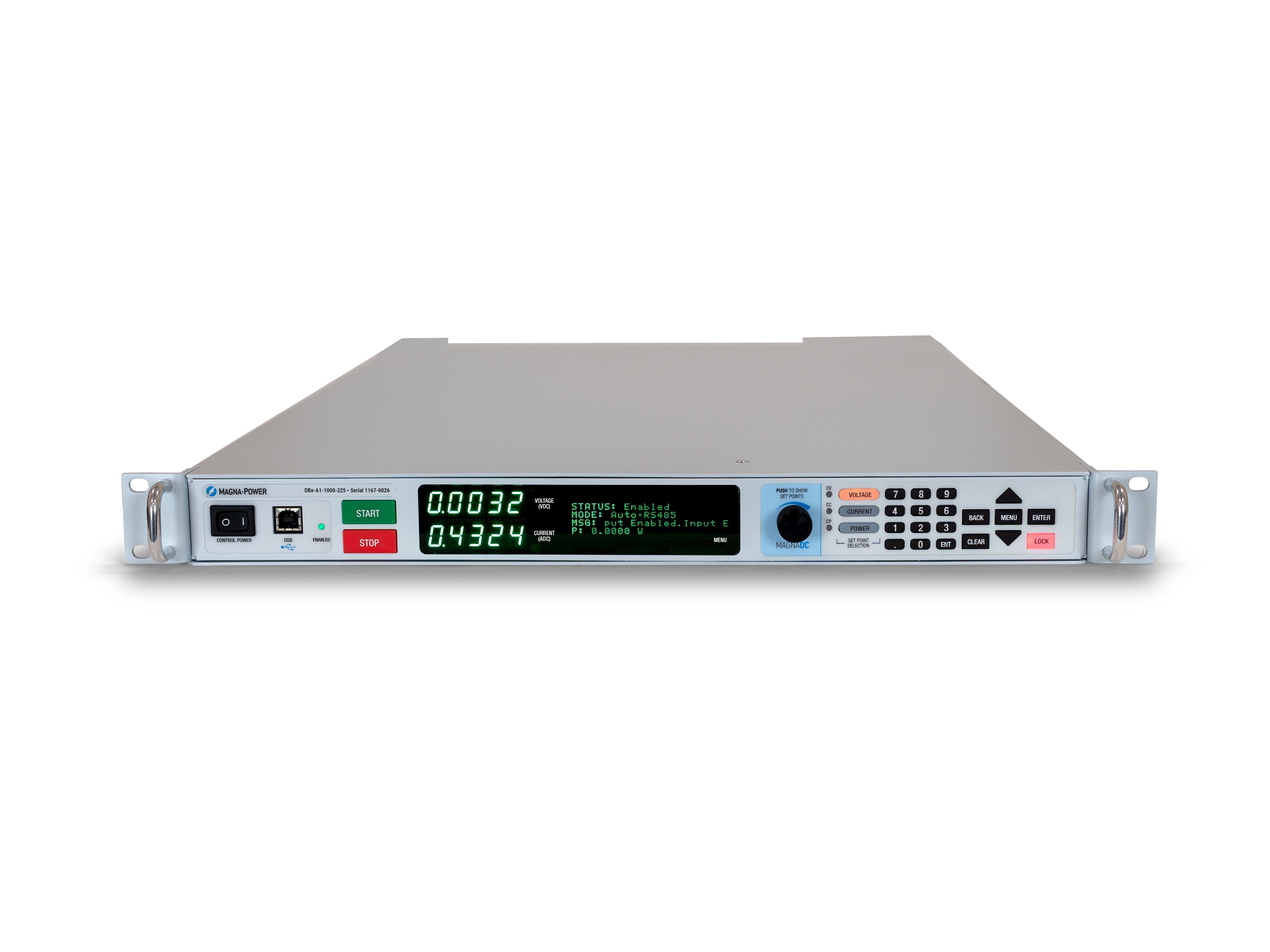
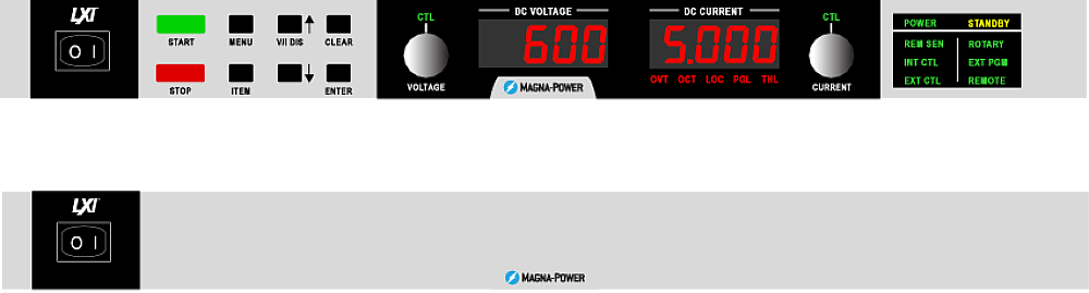
Le panneau avant SL standard offre une commande par bouton rotatif et par touches, un affichage numérique lumineux et des indicateurs d'état clairs, permettant aux opérateurs de configurer les consignes, de démarrer et d'arrêter l'alimentation, et de visualiser l'état du système en un coup d'œil. Pour les OEM et les outils de production, le panneau avant vierge en option (version C) supprime toutes les commandes locales tout en conservant un contrôle total via les interfaces de communication et le connecteur d'E/S utilisateur 37 broches en face arrière, garantissant des systèmes sécurisés, épurés et protégés contre les manipulations non autorisées.
Rugged by design: safety + reliability, as you'd expect from Magna-Power.

Traitement de puissance fiable à alimentation en courant
Robuste par conception : topologie autoprotégée pour une disponibilité maximale.
The SLx Series uses a high-frequency, current-fed architecture that adds a control stage beyond conventional voltage-fed designs. This topology inherently limits fault energy—avoiding fast-rising current spikes and magnetic core saturation so the supply self-protects and your load stays safe. Paired with state-of-the-art SiC power semiconductors, SLx delivers class-leading power density, efficiency, and reliability, including continuous full-power operation up to 50°C ambient.
- Current-fed architecture with an added control stage vs. voltage-fed.
- Inherent surge immunity—no current spikes or core saturation.
- Self-protecting behavior under fault conditions.
- SiC devices for high density and efficiency; full power to 50°C.
Caractéristiques de sécurité et verrouillage
Démarrage progressif, protection programmable et déconnexion mécanique du réseau pour une sécurité optimale.
MagnaDC supplies start gently and watch continuously. A soft-start stage keeps inrush below steady-state draw, while built-in diagnostics monitor line, thermal, and control conditions. In standby or on a diagnostic fault, an embedded AC contactor mechanically disconnects the mains, assuring the unit only processes power when intended. Faults are shown on the front-panel status display, through 5V digital outputs, and are queryable via SCPI.
-
Programmable trips: Over voltage (OVT) and over current (OCT)/
-
Control integrity: Program-line over-voltage detection.
-
Thermal protection: Over temperature on internal heatsinks.
-
Interlock/E-stop fault monitoring as a standard diagnostic.
-
Field integration: 5V interlock input (with 5V reference) for a dry-contact, latching inhibit with control power maintained.
From lab scripts to factory PLCs, flexible programming & integration.
Intégration logicielle simplifiée
Des commandes lisibles, des résultats rapides — compatible avec tout langage.
Les alimentations MagnaDC exposent une API textuelle claire avec SCPI natif, un langage de commande ASCII transmis par communications socket. Plus de 40 commandes bien documentées couvrent le démarrage/arrêt, les consignes de tension, de courant, les mesures haute précision et la configuration complète — permettant à vos scripts et systèmes de passer rapidement du prototype à la production.
- Jeux de commandes SCPI avec un comportement cohérent.
- Démarrage/arrêt et protections : activation de la sortie, réglage des seuils de déclenchement, interrogation de l'état.
- Lectures haute précision : tension, courant, puissance et retour de mesure.
- Documentation et exemples orientés développeurs.
import serial
magnaPower = serial.Serial(port='COM4', baudrate=19200)
magnaPower.write('*IDN?\n'.encode())
print magna_power.readline()
magnaPower.write('VOLT 0\n'.encode())
magnaPower.write('CURR 0\n'.encode())
magnaPower.write('OUTP:START\n'.encode())
magnaPower.write('VOLT 270\n'.encode())
currSetPoints = [50, 100, 150, 250]
for currSetPoint in currSetPoints:
    print 'Setting Current to %s A' % currSetPoint
    magnaPower.write('CURR {0}\n'.format(currSetPoint).encode())
    magnaPower.write('MEAS:VOLT?\n'.encode())
    print magnaPower.readline()
    time.sleep(20)
magnaPower.write('OUTP:STOP\n'.encode())
magnaPower.close()
magna_power = serial('COM4', 'BaudRate', 19200);
fopen(magnaPower);
fprintf(magnaPower,'*IDN?');
idn = fscanf(magnaPower);
fprintf(magnaPower,'VOLT 0');
fprintf(magnaPower,'CURR 0');
fprintf(magnaPower,'OUTP:START');
fprintf(magnaPower,'VOLT 270');
for currSetPoint in [50, 100, 150, 250]
    display('Setting Current to '+currSetPoint+' A');
    fprintf(magnaPower, 'CURR '+currSetPoint);
    fprintf(magnaPower,'MEAS:VOLT?');
    display(fscanf(magnaPower));
    pause(20);
end
#include <stdio.h>
#include <stdint.h>
#include <string.h>
#include <windows.h>

int main()
{
    printf("Opening connection.\n");

    uint8_t recvBuffer[sizeof(uint8_t) * 256];
    memset(recvBuffer, 0, 256);

    // Choose the serial port name.
    // COM ports higher than COM9 need the \\.\ prefix, which is written as
    // "\\\\.\\" in C because we need to escape the backslashes.
    const char* device = "\\\\.\\COM4";

    // Choose the baud rate (bits per second).
    uint32_t baud_rate = 19200;

    HANDLE port = open_serial_port(device, baud_rate);
    if (port == INVALID_HANDLE_VALUE) { return 1; }

    char* scpiCmd = (char*)"*IDN?\n";
    size_t cmdLen = strlen(scpiCmd);
    int result = write_port(port, (uint8_t*)scpiCmd, cmdLen);
    if (result < 0)
        return -1;

    result = read_port(port, recvBuffer, 256);
    printf("Sent: %s\nReceived: %s\n", scpiCmd, recvBuffer);

    scpiCmd = (char*)"VOLT 0\n";
    cmdLen = strlen(scpiCmd);
    result = write_port(port, (uint8_t*)scpiCmd, cmdLen);
    if (result < 0)
        return -1;

    scpiCmd = (char*)"CURR 0\n";
    cmdLen = strlen(scpiCmd);
    result = write_port(port, (uint8_t*)scpiCmd, cmdLen);
    if (result < 0)
        return -1;

    scpiCmd = (char*)"OUTP:START\n";
    cmdLen = strlen(scpiCmd);
    result = write_port(port, (uint8_t*)scpiCmd, cmdLen);
    if (result < 0)
        return -1;

    scpiCmd = (char*)"VOLT 270\n";
    cmdLen = strlen(scpiCmd);
    result = write_port(port, (uint8_t*)scpiCmd, cmdLen);
    if (result < 0)
        return -1;

    char setPoints[4][5] = {"50", "100", "150", "200"};
    char setPointBuffer[40];
    scpiCmd = (char*)"MEAS:VOLT?\n";

    for (int i = 0; i < 4; i++)
    {
        sprintf(setPointBuffer, "CURR %s\n", setPoints[i]);
        printf("Setting current to %s A\n", setPoints[i]);
        cmdLen = strlen(setPointBuffer);
        result = write_port(port, (uint8_t*)setPointBuffer, cmdLen);
        if (result < 0)
            return -1;
        memset(recvBuffer, 0, 256);
        result = read_port(port, recvBuffer, 256);
        printf("Received: %s\n", recvBuffer);
        Sleep(20000);  // 20000ms = 20s
    }

    scpiCmd = (char*)"OUTP:STOP\n";
    cmdLen = strlen(scpiCmd);
    result = write_port(port, (uint8_t*)scpiCmd, cmdLen);
    if (result < 0)
        return -1;

    CloseHandle(port);

    printf("Connection closed.\n");
    return 0;
}
using System;
using System.IO.Ports;
using System.Threading;

namespace SerialCommunicationInCSharp
{
  public class Program
  {
    static bool _continue;
    static SerialPort serialPort;

    public static void Main(string[] args)
    {
      Thread readThread = new Thread(Read);

      Console.WriteLine("Opening connection.");

      // Create a new SerialPort object with default settings.
      serialPort = new SerialPort("COM4", 19200, Parity.None, 8, StopBits.One);

      // Set the read/write timeouts
      serialPort.ReadTimeout = 500;
      serialPort.WriteTimeout = 500;

      serialPort.Open();
      _continue = true;
      readThread.Start();

      Console.WriteLine("Sending: *IDN?");
      serialPort.WriteLine("*IDN?");

      serialPort.WriteLine("VOLT 0");
      serialPort.WriteLine("CURR 0");
      serialPort.WriteLine("OUTP:START");
      serialPort.WriteLine("VOLT 270");

      string[] currSetPoints = { "50", "100", "150", "250" };
ß
      for(int i = 0; i < currSetPoints.Length; i++)
      {
        serialPort.WriteLine(String.Format("'CURR {0}", currSetPoints[i]));
        serialPort.WriteLine("MEAS:VOLT?");
        Thread.Sleep(20000);
      }

      serialPort.WriteLine("OUTP:STOP");

      Console.WriteLine("Closing connection.");
      _continue = false;
      serialPort.Close();
      }

    public static void Read()
    {
      while (_continue)
      {
        try
        {
          string message = serialPort.ReadLine();
          Console.WriteLine("Received: " + message);
        }
        catch (TimeoutException) { }
      }
    }
  }
}

E/S utilisateur externes pour le contrôle par automate ou la simulation PHIL
Câblez-le comme un module d'E/S—aucune isolation supplémentaire nécessaire.
Via the included rear 37-pin User I/O connector, MagnaDC supplies can be fully driven and monitored by external signals or a PLC. Voltage, current, OVT, and OCT set points are programmed with 0–10 V analog inputs, while each diagnostic condition has its own +5V digital status pin. Built-in +2.5V, +5V, and +10V reference rails let you use dry contacts without adding external supplies. All I/O is isolated from the output and referenced to earth ground as standard.
-
0–10 V analog programming for V, I, OVT, and OCT.
-
Per-fault digital outputs: each diagnostic has its own +5V pin.
-
Isolated user I/O referenced to earth ground—no extra isolators.
-
With High Slew Rate Output (+HS), high-bandwidth response and fast rise times support HIL/PHIL simulation applications.
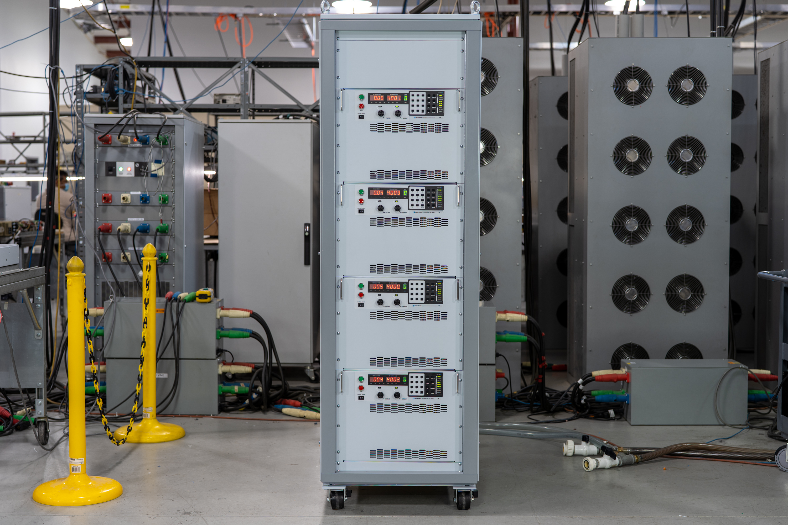
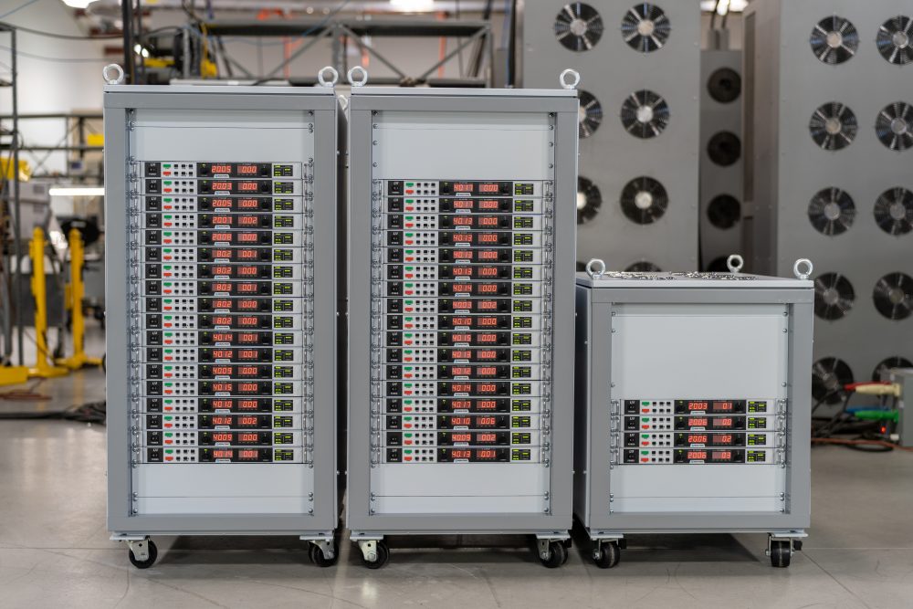
Fonctionnement maître-esclave haute performance
Augmentez la tension ou le courant sans sacrifier les performances.
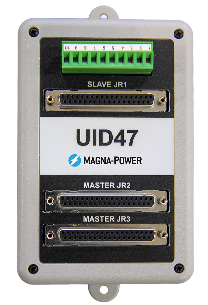
All MagnaDC supplies support master-slave operation, using gate-drive signals from the master when configured for parallel, so the whole stack behaves like a single supply—with one control loop and no noisy long analog references. The optional UID47 accessory simplifies wiring for series or parallel sets with near-equal sharing.
-
Single control loop parallel operation: Master gate-drive to slaves for consistent dynamics.
-
Plug & play with the UID47, enabling parallel or series stacks with current/voltage sharing.
-
Series up to the DC isolation rating without added hardware.
No additional ORing diodes required for parallel operation.
Logiciels, pilotes LabVIEW & IVI Magna-Power
Du panneau avant virtuel à l'automatisation complète — prêt à l'emploi.
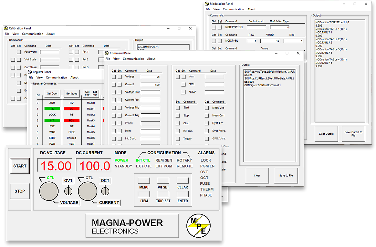
Chaque alimentation MagnaDC inclut un pilote IVI et un pilote NI LabVIEW avec un ensemble complet de VIs, ainsi que des programmes d'exemple pour communiquer avec le matériel en quelques minutes. Pour un contrôle direct de type panneau avant depuis un PC, le logiciel Remote Interface Software de Magna-Power offre une vue complète de l'alimentation — des commandes et registres à la calibration et au firmware.
-
Pilotes IVI et NI LabVIEW inclus avec un ensemble complet de VIs.
-
Programmes d'exemple pour démarrer rapidement l'intégration et les tests.
-
Remote Interface Software avec :
-
Panneau avant virtuel pour le contrôle manuel
-
Panneau de commandes pour explorer et envoyer des commandes
-
Panneau de registres pour la surveillance en temps réel
-
Panneau de calibration pour les potentiomètres numériques internes
-
Panneau firmware pour les mises à jour sur place
-
Panneau de modulation pour émuler des profils non linéaires
-
-
Toutes les interfaces de communication prises en charge par les logiciels et pilotes pour une expérience de programmation cohérente.
State-of-the-art USA manufacturing with worldwide support

Made in the USA
Fabrication verticalement intégrée pour un contrôle qualité total.
Les produits Magna-Power sont conçus, fabriqués, testés et entretenus au siège de Magna-Power, d'une superficie de 73 500 sq-ft à Flemington, New Jersey, où la métallurgie, les composants magnétiques, l'assemblage des PCB et le rodage sont tous réalisés en interne pour un contrôle rigoureux de la qualité, des coûts et des délais.
- Fabriqué aux USA : Ingénierie, fabrication et service sous un même toit.
- Production en interne : Métallurgie, composants magnétiques, PCB SMT et finitions.
- Fiabilité éprouvée : Chaque unité est entièrement testée, calibrée et rodée.
Service mondial et support de pièces OEM
Expertise d'usine, réponse locale.
Magna-Power garantit ses produits grâce à des centres de service agréés en usine à travers l'Amérique du Nord, l'Europe, le Royaume-Uni, l'Asie-Pacifique, l'Asie de l'Est et l'Amérique du Sud — utilisant des procédures d'usine et des pièces d'origine pour remettre les unités aux spécifications d'origine, sous garantie ou hors garantie.
- Couverture mondiale : siège social dans le New Jersey et centres de service agréés régionaux.
- Réparations homogènes : diagnostics d'usine, instructions de travail et schémas système.
- Pièces OEM d'origine : assemblages de remplacement testés pour un service prévisible et à faible temps d'arrêt.
Model Ordering Guide
For both ordering and production, SL Series models are uniquely defined by several key characteristics, as defined by the following diagram:

SL Series Models
There are 127 different models in the SL Series spanning power levels: 1.5 kW, 2.6 kW, 4 kW, 6 kW, 8 kW, 10 kW. To determine the appropriate model:
- Select the desired Max Voltage (Vdc) from the left-most column.
- Select the desired Max Current (Adc) from the same row that contains your desired Max Voltage.
- Construct your model number according to the model ordering guide.
| Max Voltage Vdc |
1.5 kW | 2.6 kW | 4 kW | 6 kW | 8 kW | 10 kW | Ripple mVrms |
Efficiency |
|---|---|---|---|---|---|---|---|---|
| Max Current Adc | ||||||||
| 5 | 250 | — | — | — | — | — | 30 | 84% |
| 10 | 150 | 250 | — | — | — | — | 30 | 89% |
| 16 | 93 | 162 | 250 | — | — | — | 40 | 89% |
| 20 | 75 | 130 | 200 | 250 | — | — | 40 | 90% |
| 25 | 60 | 104 | 160 | 240 | — | — | 50 | 91% |
| 32 | 46 | 81 | 125 | 186 | 250 | — | 60 | 91% |
| 40 | 37 | 65 | 100 | 150 | 200 | 250 | 80 | 91% |
| 50 | 30 | 52 | 80 | 120 | 160 | 200 | 70 | 92% |
| 60 | 25 | 43 | 66 | 100 | 133 | 166 | 100 | 93% |
| 80 | 18 | 32 | 50 | 75 | 100 | 125 | 120 | 93% |
| 100 | 15 | 26 | 40 | 60 | 80 | 100 | 120 | 93% |
| 125 | 12 | 20 | 32 | 48 | 64 | 80 | 110 | 93% |
| 160 | 9 | 16 | 25 | 36 | 50 | 60 | 110 | 93% |
| 200 | 7.5 | 13 | 20 | 30 | 40 | 50 | 110 | 94% |
| 250 | 6 | 10.4 | 16 | 24 | 32 | 40 | 110 | 94% |
| 300 | 5 | 8.6 | 13.2 | 20 | 26.4 | 33.3 | 120 | 94% |
| 375 | 4 | 6.9 | 10.4 | 16 | 21.3 | 26.5 | 120 | 94% |
| 400 | 3.7 | 6.5 | 10 | 15 | 20 | 25 | 170 | 95% |
| 500 | 3 | 5.2 | 8 | 12 | 16 | 20 | 250 | 95% |
| 600 | 2.5 | 4.3 | 6.4 | 10 | 13.3 | 16.5 | 250 | 95% |
| 800 | 1.8 | 3.2 | 5 | 7.5 | 10 | 12.5 | 250 | 95% |
| 1000 | 1.5 | 2.6 | 4 | 6 | 8 | 10 | 400 | 95% |
| 1250 | 1.2 | 2 | 3.2 | 4.8 | 6.4 | 8 | 700 | 95% |
| 1500 | 1 | 1.7 | 2.6 | 4 | 5.3 | 6.6 | 1000 | 95% |
| AC Input Voltage Vac |
Input Current Per Phase Aac | |||||||
| UI (85-265 Vac, 1Φ) | 21 - 7 | — | — | — | — | — | ||
| UI2 (187-265 Vac, 1Φ) | — | 16 - 12 | — | — | — | — | ||
| 208/240 Vac, 3Φ | 6 | 11 | 16 | 24 | 32 | 39 | ||
| 380/415 Vac, 3Φ | 5 | 8 | 11 | 16 | 19 | 22 | ||
| 440/480 Vac, 3Φ | 4 | 6 | 9 | 14 | 17 | 19 | ||
Specifications are subject to change without notice. Unless otherwise noted, all specifications measured at the product's maximum ratings.
AC Input Specifications
208-240 Vac (UI2: Universal input 2; 2.6 kW Models)
240 Vac (operating range 216 to 264 Vac)
380 Vac (operating range 342 to 440 Vac)
415 Vac (operating range 373 to 456 Vac)
440 Vac (operating range 396 to 484 Vac)
480 Vac (operating range 432 to 528 Vac)
> 0.82 at maximum power for models with 3Φ AC input
DC Output Specifications
Current mode: ± 0.02% of full scale
Current mode: ± 0.04% of full scale
Model specific. Refer to chart of available models.
< 200 ms for a programmed output current change from 0 to 63%
< 10 ms for a programmed output current change from 0 to 63%
2 Hz with remote analog current programming
45 Hz with remote analog current programming
Programming Interface Specifications
LXI TCP/IP Ethernet RJ45 (Option +LXI)
IEEE-488 GPIB (Option +GPIB)
Referenced to Earth ground; isolated from power supply output
See User Manual for pin layout
Accuracy Specifications
External User I/O Specifications
Current output monitoring: 100 Ω
+10V reference: 1 Ω
Output: 0 to 5 Vdc, 5 mA drive capacity
Physical Specifications
1.75" H x 19" W x 24" D (4.4 x 48.3 x 61.0 cm)
32 lbs (14.52 kg)
1.75" H x 19" W x 24" D (4.4 x 48.3 x 61.0 cm)
34 lbs (15.42 kg)
1.75" H x 19" W x 24" D (4.4 x 48.3 x 61.0 cm)
35 lbs (15.88 kg)
1.75" H x 19" W x 24" D (4.4 x 48.3 x 61.0 cm)
35 lbs (15.88 kg)
1.75" H x 19" W x 24" D (4.4 x 48.3 x 61.0 cm)
36 lbs (16.33 kg)
1.75" H x 19" W x 24" D (4.4 x 48.3 x 61.0 cm)
37 lbs (16.78 kg)
Environmental Specifications
0.06%/°C of maximum output current
Regulatory Specifications
CISPR 22 / EN 55022 Class A
CSA C22.2 No. 61010-1:12; A1:2018
UL 61010-1:Ed.3,2012(R2019)
The following are vectorized diagrams for the SL Series. Refer to the Downloads section for downloadable drawings.


Integrated Options
Standard integrated options are available for Magna-Power products, allowing the product's performance and communication interfaces to be tailors to the specific application.
- Option
- +HS
- Option
- +GPIB

Accessories
External accessories and integration services available for this product.