SL系列
Programmable DC Power Supply
- Size
- 1U
- Power
- 1.5 kW to 10 kW
- Manufactured
- USA
- Build-time
- 4-6 weeks
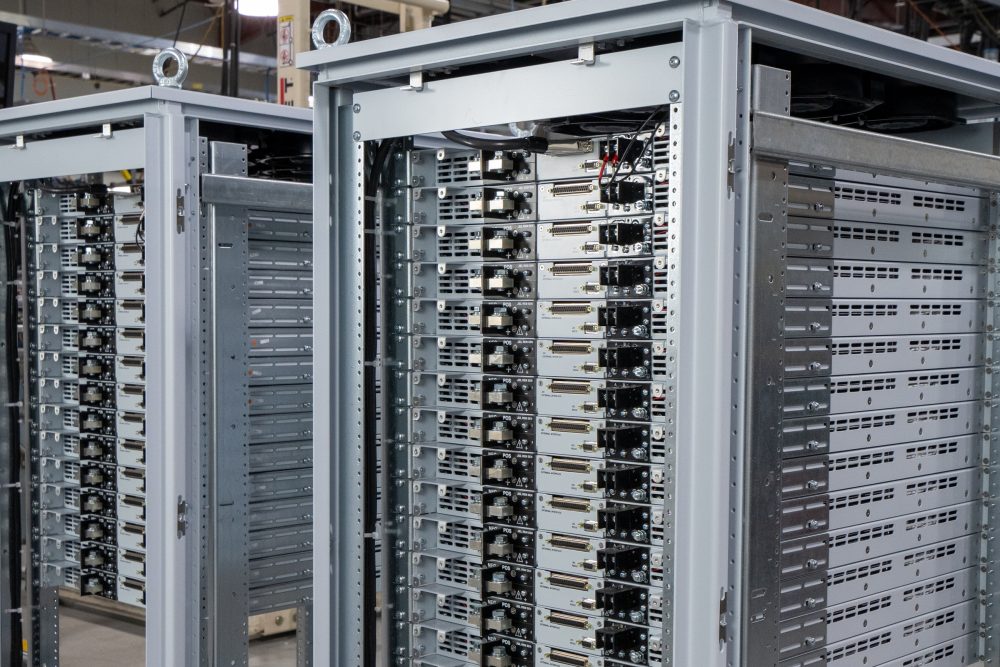
The SL Series builds on over 40 years of power supply innovation at Magna-Power, designed from the ground up to meet the highly reliable power dense demands of ATE system integrators through Magna-Power's signature current-fed power processing topology. Utilizing state-of-the-art semiconductors and innovative internally designed and manufactured heat sinks, the SL Series offers industry-leading 1U (1.75” height) programmable power levels with models at 1.5 kW, 2.6 kW, 4 kW, 6 kW, 8 kW, and 10 kW while still maintaining an ambient operating temperature rating up to 50°C.

Talk with an expert


Fast, accurate power delivery with controls and options tailored to your needs
无与伦比的1U功率与性能
清洁、精确的输出,快速响应,满足严苛系统需求。
SL系列电源具备快速瞬态响应、高精度编程与测量、12位分辨率以及低输出纹波——所有这些均集成于业界领先的1U机箱中,效率高达95%。凭借恒压或恒流运行模式及自动切换功能,其在负载阶跃后能够快速稳定(负载瞬态恢复时间在几毫秒量级),并精确锁定目标值,电压和电流编程精度高达满量程的±0.075%——是精密测试、老化试验和工艺应用的理想选择,在动态性能和精度方面均表现出色。
按需配置,集成多种选项
丰富的标准功能,按需扩展。
SL Series starts with a strong base: SCPI over RS232, isolated 37-pin user I/O, LabVIEW and IVI drivers, and Remote Interface Software included. When applications demand more, fully integrated options tailor performance, connectivity, and mechanics—without external boxes or ad-hoc wiring.
Standard SCPI computer controls, RS232, isolated 37-pin analog/digital I/O, LabVIEW & IVI drivers, RIS software.
-
High Slew Rate Output (+HS) for higher bandwidth and faster programmed rise times.
-
Connectivity options LXI TCP/IP Ethernet (+LXI) and IEEE-488 GPIB (+GPIB).
-
Ruggedized (+RUG) for MIL-STD shock & vibration
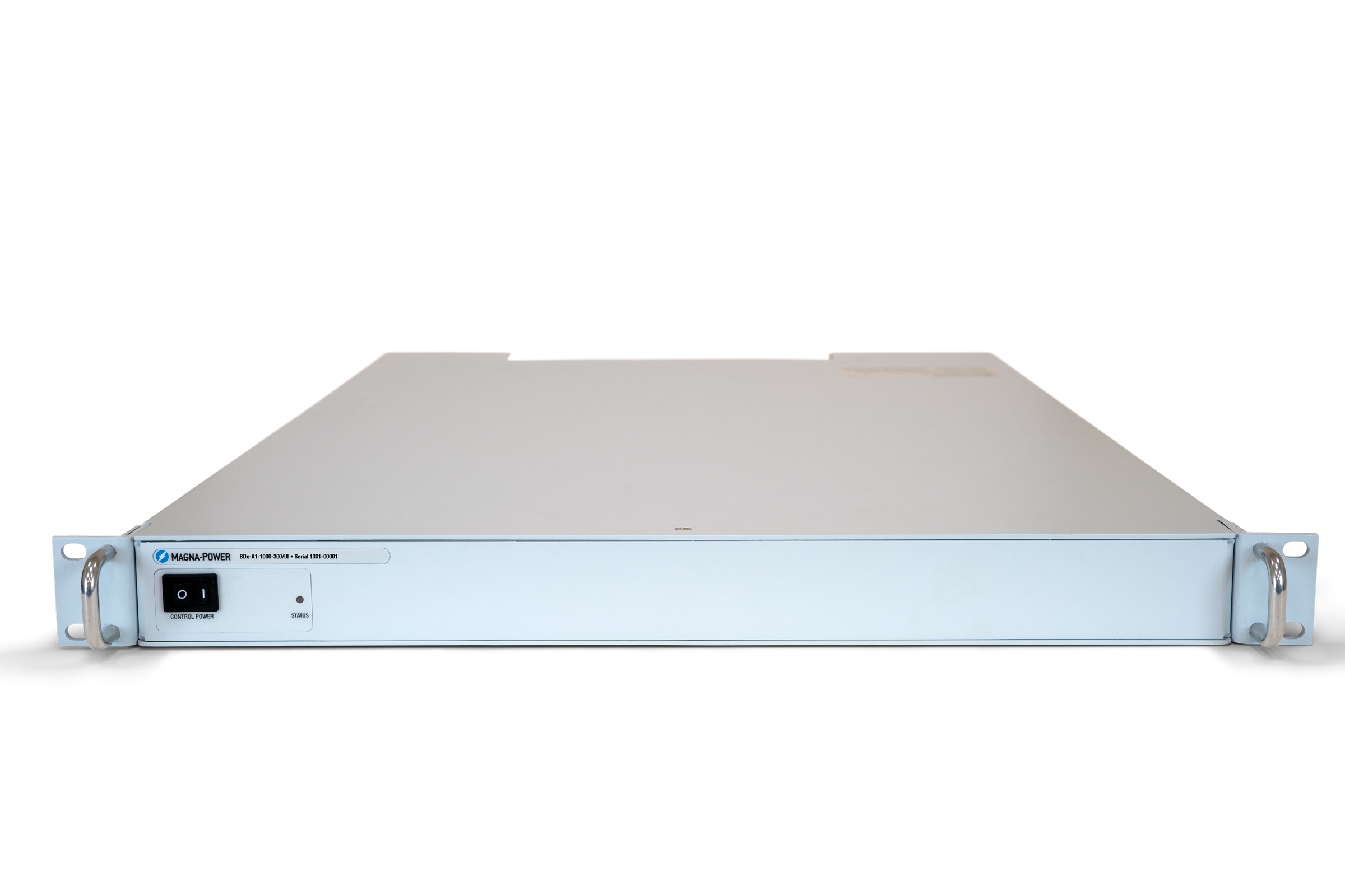
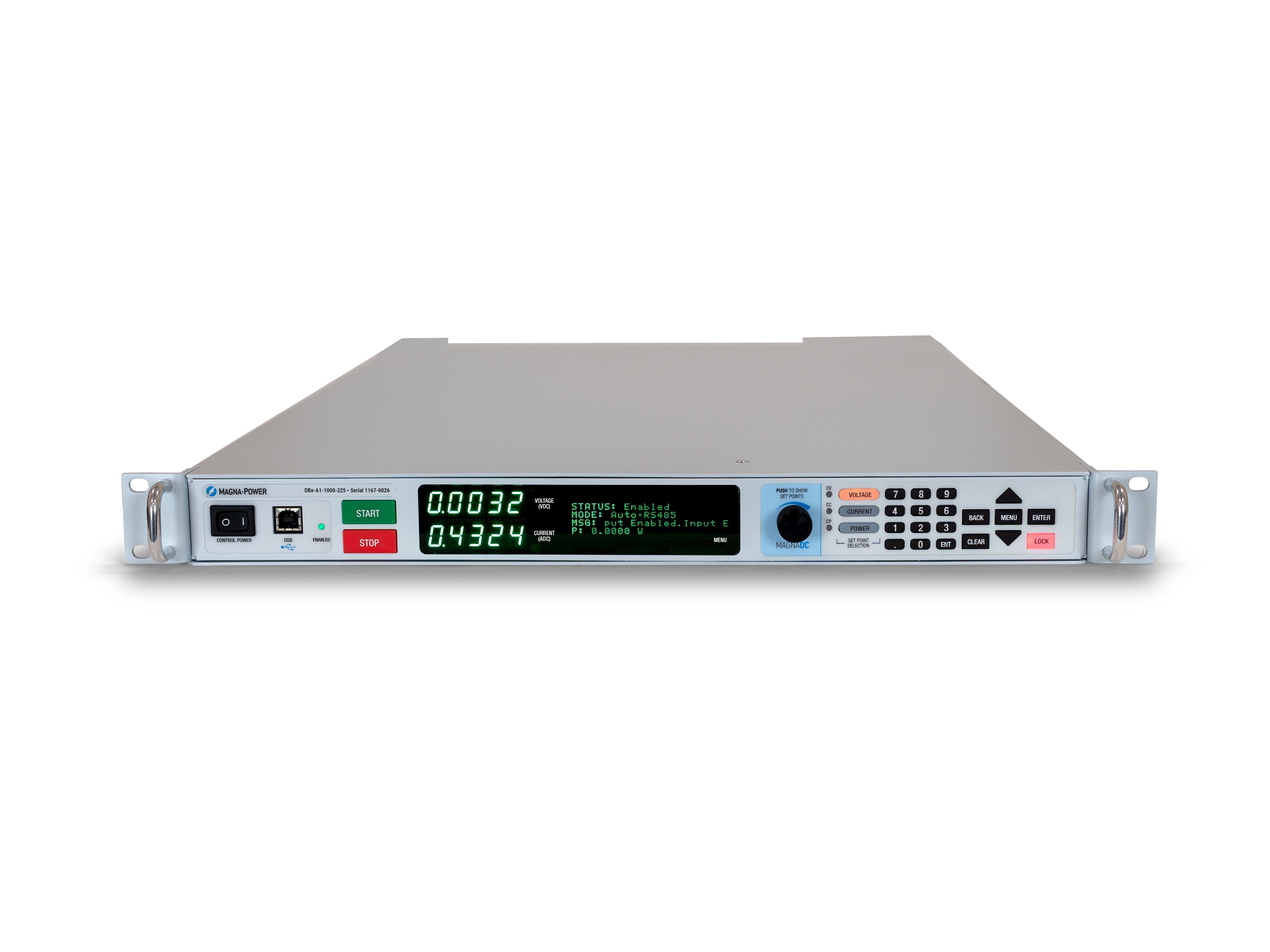
无级前面板控制,可选空白面板
需要操控时触手可及,无需时隐于无形。
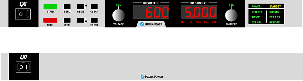
标准SL前面板配备旋钮和按键控制、高亮数字仪表及清晰的状态指示灯,操作人员可轻松配置设定值、启停电源,并一目了然地掌握系统运行状态。针对OEM客户和生产设备,可选的空白面板(C版本)完全取消了本地控制功能,同时通过通信接口和后部37针用户I/O保留完整的远程控制能力,确保系统安全、整洁且防止误操作。
Rugged by design: safety + reliability, as you'd expect from Magna-Power.

可靠的电流馈电功率处理
坚固耐用的设计:自保护拓扑结构,确保持续运行。
The SLx Series uses a high-frequency, current-fed architecture that adds a control stage beyond conventional voltage-fed designs. This topology inherently limits fault energy—avoiding fast-rising current spikes and magnetic core saturation so the supply self-protects and your load stays safe. Paired with state-of-the-art SiC power semiconductors, SLx delivers class-leading power density, efficiency, and reliability, including continuous full-power operation up to 50°C ambient.
- Current-fed architecture with an added control stage vs. voltage-fed.
- Inherent surge immunity—no current spikes or core saturation.
- Self-protecting behavior under fault conditions.
- SiC devices for high density and efficiency; full power to 50°C.
安全功能与互锁
软启动、可编程保护以及机械线路断开装置,提供真正的安全保障。
MagnaDC supplies start gently and watch continuously. A soft-start stage keeps inrush below steady-state draw, while built-in diagnostics monitor line, thermal, and control conditions. In standby or on a diagnostic fault, an embedded AC contactor mechanically disconnects the mains, assuring the unit only processes power when intended. Faults are shown on the front-panel status display, through 5V digital outputs, and are queryable via SCPI.
-
Programmable trips: Over voltage (OVT) and over current (OCT)/
-
Control integrity: Program-line over-voltage detection.
-
Thermal protection: Over temperature on internal heatsinks.
-
Interlock/E-stop fault monitoring as a standard diagnostic.
-
Field integration: 5V interlock input (with 5V reference) for a dry-contact, latching inhibit with control power maintained.
From lab scripts to factory PLCs, flexible programming & integration.
轻松实现软件集成
可读命令,快速响应——兼容任何编程语言。
MagnaDC 电源提供清晰的文本API接口,支持原生SCPI——一种通过套接字通信发送的ASCII命令语言。超过40条详细文档化的命令涵盖启动/停止、电压和电流设定值、高精度测量以及完整配置——让您的脚本和系统从概念验证快速迈向生产部署。
- SCPI命令集,行为一致可靠。
- 启动/停止与保护功能:启用输出、设置跳闸限值、查询状态。
- 高精度读取:电压、电流、功率及检测反馈。
- 面向开发者的文档与示例。
import serial
magnaPower = serial.Serial(port='COM4', baudrate=19200)
magnaPower.write('*IDN?\n'.encode())
print magna_power.readline()
magnaPower.write('VOLT 0\n'.encode())
magnaPower.write('CURR 0\n'.encode())
magnaPower.write('OUTP:START\n'.encode())
magnaPower.write('VOLT 270\n'.encode())
currSetPoints = [50, 100, 150, 250]
for currSetPoint in currSetPoints:
    print 'Setting Current to %s A' % currSetPoint
    magnaPower.write('CURR {0}\n'.format(currSetPoint).encode())
    magnaPower.write('MEAS:VOLT?\n'.encode())
    print magnaPower.readline()
    time.sleep(20)
magnaPower.write('OUTP:STOP\n'.encode())
magnaPower.close()
magna_power = serial('COM4', 'BaudRate', 19200);
fopen(magnaPower);
fprintf(magnaPower,'*IDN?');
idn = fscanf(magnaPower);
fprintf(magnaPower,'VOLT 0');
fprintf(magnaPower,'CURR 0');
fprintf(magnaPower,'OUTP:START');
fprintf(magnaPower,'VOLT 270');
for currSetPoint in [50, 100, 150, 250]
    display('Setting Current to '+currSetPoint+' A');
    fprintf(magnaPower, 'CURR '+currSetPoint);
    fprintf(magnaPower,'MEAS:VOLT?');
    display(fscanf(magnaPower));
    pause(20);
end
#include <stdio.h>
#include <stdint.h>
#include <string.h>
#include <windows.h>

int main()
{
    printf("Opening connection.\n");

    uint8_t recvBuffer[sizeof(uint8_t) * 256];
    memset(recvBuffer, 0, 256);

    // Choose the serial port name.
    // COM ports higher than COM9 need the \\.\ prefix, which is written as
    // "\\\\.\\" in C because we need to escape the backslashes.
    const char* device = "\\\\.\\COM4";

    // Choose the baud rate (bits per second).
    uint32_t baud_rate = 19200;

    HANDLE port = open_serial_port(device, baud_rate);
    if (port == INVALID_HANDLE_VALUE) { return 1; }

    char* scpiCmd = (char*)"*IDN?\n";
    size_t cmdLen = strlen(scpiCmd);
    int result = write_port(port, (uint8_t*)scpiCmd, cmdLen);
    if (result < 0)
        return -1;

    result = read_port(port, recvBuffer, 256);
    printf("Sent: %s\nReceived: %s\n", scpiCmd, recvBuffer);

    scpiCmd = (char*)"VOLT 0\n";
    cmdLen = strlen(scpiCmd);
    result = write_port(port, (uint8_t*)scpiCmd, cmdLen);
    if (result < 0)
        return -1;

    scpiCmd = (char*)"CURR 0\n";
    cmdLen = strlen(scpiCmd);
    result = write_port(port, (uint8_t*)scpiCmd, cmdLen);
    if (result < 0)
        return -1;

    scpiCmd = (char*)"OUTP:START\n";
    cmdLen = strlen(scpiCmd);
    result = write_port(port, (uint8_t*)scpiCmd, cmdLen);
    if (result < 0)
        return -1;

    scpiCmd = (char*)"VOLT 270\n";
    cmdLen = strlen(scpiCmd);
    result = write_port(port, (uint8_t*)scpiCmd, cmdLen);
    if (result < 0)
        return -1;

    char setPoints[4][5] = {"50", "100", "150", "200"};
    char setPointBuffer[40];
    scpiCmd = (char*)"MEAS:VOLT?\n";

    for (int i = 0; i < 4; i++)
    {
        sprintf(setPointBuffer, "CURR %s\n", setPoints[i]);
        printf("Setting current to %s A\n", setPoints[i]);
        cmdLen = strlen(setPointBuffer);
        result = write_port(port, (uint8_t*)setPointBuffer, cmdLen);
        if (result < 0)
            return -1;
        memset(recvBuffer, 0, 256);
        result = read_port(port, recvBuffer, 256);
        printf("Received: %s\n", recvBuffer);
        Sleep(20000);  // 20000ms = 20s
    }

    scpiCmd = (char*)"OUTP:STOP\n";
    cmdLen = strlen(scpiCmd);
    result = write_port(port, (uint8_t*)scpiCmd, cmdLen);
    if (result < 0)
        return -1;

    CloseHandle(port);

    printf("Connection closed.\n");
    return 0;
}
using System;
using System.IO.Ports;
using System.Threading;

namespace SerialCommunicationInCSharp
{
  public class Program
  {
    static bool _continue;
    static SerialPort serialPort;

    public static void Main(string[] args)
    {
      Thread readThread = new Thread(Read);

      Console.WriteLine("Opening connection.");

      // Create a new SerialPort object with default settings.
      serialPort = new SerialPort("COM4", 19200, Parity.None, 8, StopBits.One);

      // Set the read/write timeouts
      serialPort.ReadTimeout = 500;
      serialPort.WriteTimeout = 500;

      serialPort.Open();
      _continue = true;
      readThread.Start();

      Console.WriteLine("Sending: *IDN?");
      serialPort.WriteLine("*IDN?");

      serialPort.WriteLine("VOLT 0");
      serialPort.WriteLine("CURR 0");
      serialPort.WriteLine("OUTP:START");
      serialPort.WriteLine("VOLT 270");

      string[] currSetPoints = { "50", "100", "150", "250" };
ß
      for(int i = 0; i < currSetPoints.Length; i++)
      {
        serialPort.WriteLine(String.Format("'CURR {0}", currSetPoints[i]));
        serialPort.WriteLine("MEAS:VOLT?");
        Thread.Sleep(20000);
      }

      serialPort.WriteLine("OUTP:STOP");

      Console.WriteLine("Closing connection.");
      _continue = false;
      serialPort.Close();
      }

    public static void Read()
    {
      while (_continue)
      {
        try
        {
          string message = serialPort.ReadLine();
          Console.WriteLine("Received: " + message);
        }
        catch (TimeoutException) { }
      }
    }
  }
}

用于PLC控制或PHIL仿真的外部用户 I/O
像I/O模块一样接线——无需额外隔离。
Via the included rear 37-pin User I/O connector, MagnaDC supplies can be fully driven and monitored by external signals or a PLC. Voltage, current, OVT, and OCT set points are programmed with 0–10 V analog inputs, while each diagnostic condition has its own +5V digital status pin. Built-in +2.5V, +5V, and +10V reference rails let you use dry contacts without adding external supplies. All I/O is isolated from the output and referenced to earth ground as standard.
-
0–10 V analog programming for V, I, OVT, and OCT.
-
Per-fault digital outputs: each diagnostic has its own +5V pin.
-
Isolated user I/O referenced to earth ground—no extra isolators.
-
With High Slew Rate Output (+HS), high-bandwidth response and fast rise times support HIL/PHIL simulation applications.
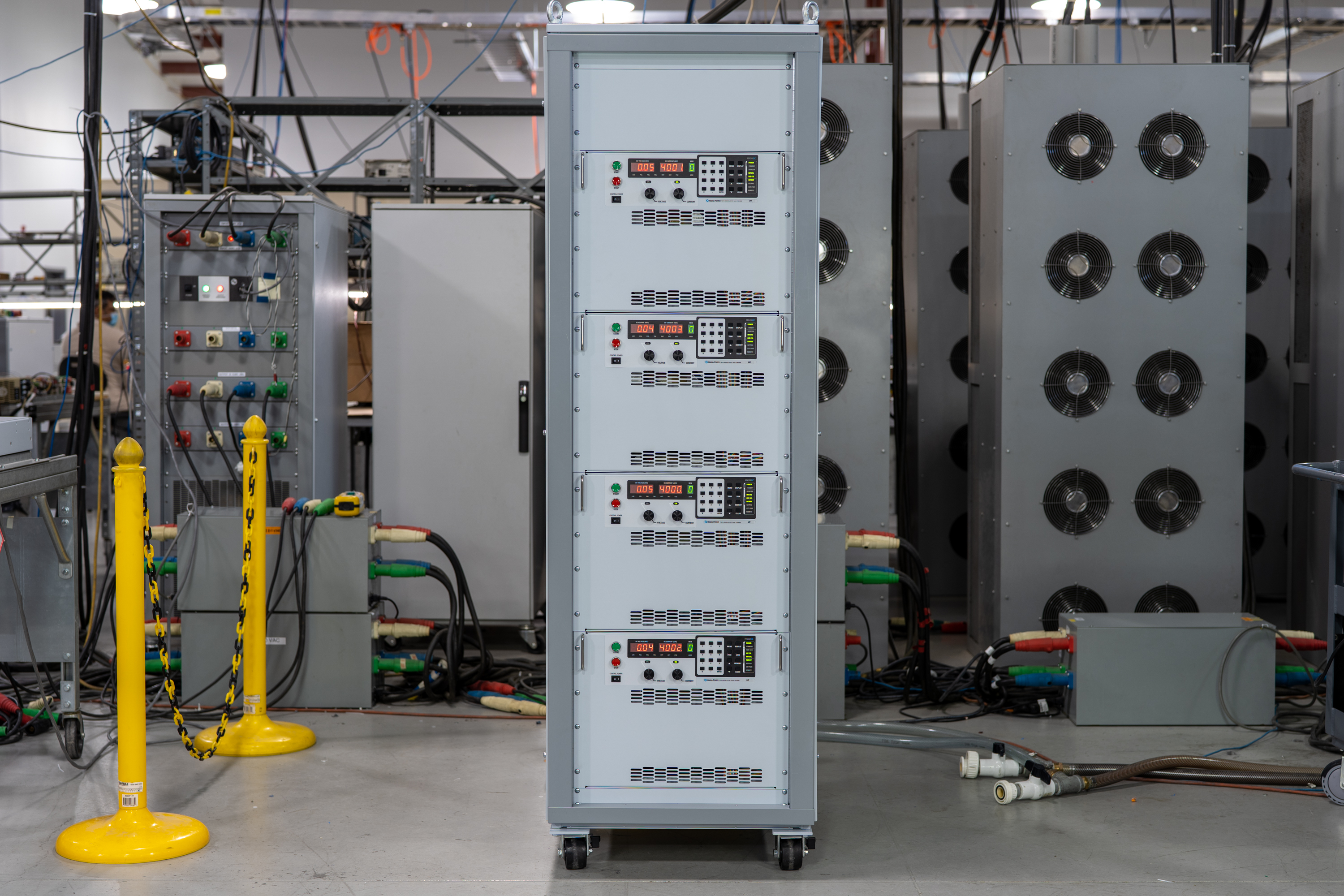
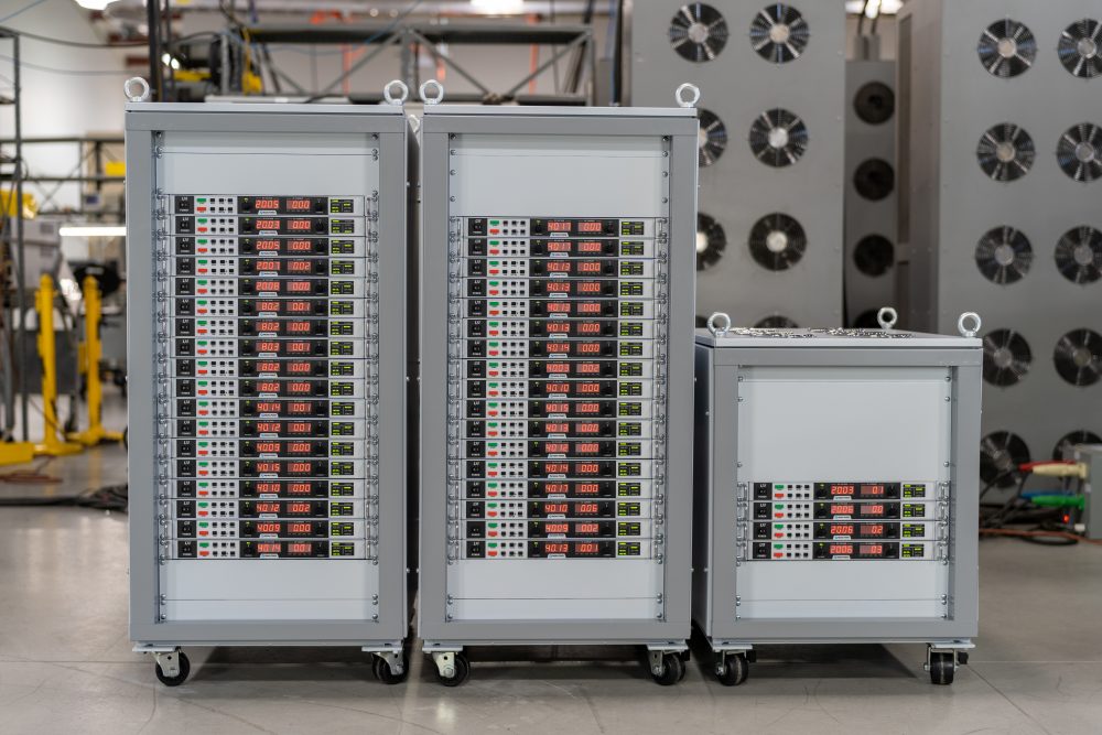
高性能主从操作
在不牺牲性能的前提下扩展电压或电流。
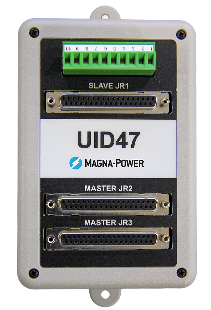
All MagnaDC supplies support master-slave operation, using gate-drive signals from the master when configured for parallel, so the whole stack behaves like a single supply—with one control loop and no noisy long analog references. The optional UID47 accessory simplifies wiring for series or parallel sets with near-equal sharing.
-
Single control loop parallel operation: Master gate-drive to slaves for consistent dynamics.
-
Plug & play with the UID47, enabling parallel or series stacks with current/voltage sharing.
-
Series up to the DC isolation rating without added hardware.
No additional ORing diodes required for parallel operation.
Magna-Power 软件、LabVIEW 和 IVI 驱动程序
从虚拟前面板到全自动化——开箱即用。
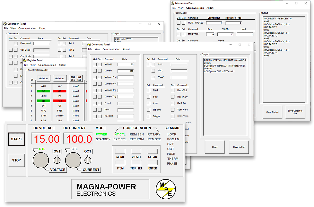
每台 MagnaDC 电源均包含 IVI 驱动程序和 NI LabVIEW 驱动程序,提供完整的 VI 集以及示例程序,让您在几分钟内即可与硬件通信。如需通过 PC 进行直接的前面板式控制,Magna-Power 远程接口软件可提供电源的全面视图——从命令和寄存器到校准和固件。
-
随附 IVI 和 NI LabVIEW 驱动程序及完整 VI 集。
-
示例程序助您快速启动集成和测试。
-
远程接口软件包含:
-
虚拟前面板,用于手动控制
-
命令面板,用于浏览和发送命令
-
寄存器面板,用于实时状态监控
-
校准面板,用于内部数字电位器
-
固件面板,用于就地升级
-
调制面板,用于模拟非线性曲线
-
-
所有通信接口在软件和驱动程序中均受支持,提供一致的编程体验。
State-of-the-art USA manufacturing with worldwide support

美国制造
垂直整合制造,实现全面质量管控。
Magna-Power 产品的设计、制造、测试和售后服务均在位于新泽西州弗莱明顿的 Magna-Power 总部完成,总部面积达 73,500 平方英尺。金属加工、磁性元件制造、PCB 组装和老化测试均在内部完成,从而严格把控质量、成本和交货周期。
- 美国制造:工程设计、生产制造和售后服务集于一处。
- 内部生产:金属加工、磁性元件、SMT PCB 和表面处理。
- 可靠性验证:每台设备均经过全面测试、校准和老化试验。
全球服务与OEM零部件支持
工厂级专业技术,本地化响应。
Magna-Power以工厂及授权服务中心为其产品提供全面支持,服务网络覆盖北美、欧洲、英国、亚太、东亚及南美地区。无论是否在保修期内,均采用工厂标准流程和原厂零部件,将设备恢复至出厂规格。
- 全球覆盖:总部位于新泽西州,并设有多个区域授权服务中心。
- 一致的维修标准:采用工厂诊断流程、作业指导书和系统图纸。
- 原厂OEM零部件:经过测试的替换组件,确保可靠、高效的维修服务,最大限度减少停机时间。
Model Ordering Guide
For both ordering and production, SL Series models are uniquely defined by several key characteristics, as defined by the following diagram:

SL Series Models
There are 127 different models in the SL Series spanning power levels: 1.5 kW, 2.6 kW, 4 kW, 6 kW, 8 kW, 10 kW. To determine the appropriate model:
- Select the desired Max Voltage (Vdc) from the left-most column.
- Select the desired Max Current (Adc) from the same row that contains your desired Max Voltage.
- Construct your model number according to the model ordering guide.
| Max Voltage Vdc |
1.5 kW | 2.6 kW | 4 kW | 6 kW | 8 kW | 10 kW | Ripple mVrms |
Efficiency |
|---|---|---|---|---|---|---|---|---|
| Max Current Adc | ||||||||
| 5 | 250 | — | — | — | — | — | 30 | 84% |
| 10 | 150 | 250 | — | — | — | — | 30 | 89% |
| 16 | 93 | 162 | 250 | — | — | — | 40 | 89% |
| 20 | 75 | 130 | 200 | 250 | — | — | 40 | 90% |
| 25 | 60 | 104 | 160 | 240 | — | — | 50 | 91% |
| 32 | 46 | 81 | 125 | 186 | 250 | — | 60 | 91% |
| 40 | 37 | 65 | 100 | 150 | 200 | 250 | 80 | 91% |
| 50 | 30 | 52 | 80 | 120 | 160 | 200 | 70 | 92% |
| 60 | 25 | 43 | 66 | 100 | 133 | 166 | 100 | 93% |
| 80 | 18 | 32 | 50 | 75 | 100 | 125 | 120 | 93% |
| 100 | 15 | 26 | 40 | 60 | 80 | 100 | 120 | 93% |
| 125 | 12 | 20 | 32 | 48 | 64 | 80 | 110 | 93% |
| 160 | 9 | 16 | 25 | 36 | 50 | 60 | 110 | 93% |
| 200 | 7.5 | 13 | 20 | 30 | 40 | 50 | 110 | 94% |
| 250 | 6 | 10.4 | 16 | 24 | 32 | 40 | 110 | 94% |
| 300 | 5 | 8.6 | 13.2 | 20 | 26.4 | 33.3 | 120 | 94% |
| 375 | 4 | 6.9 | 10.4 | 16 | 21.3 | 26.5 | 120 | 94% |
| 400 | 3.7 | 6.5 | 10 | 15 | 20 | 25 | 170 | 95% |
| 500 | 3 | 5.2 | 8 | 12 | 16 | 20 | 250 | 95% |
| 600 | 2.5 | 4.3 | 6.4 | 10 | 13.3 | 16.5 | 250 | 95% |
| 800 | 1.8 | 3.2 | 5 | 7.5 | 10 | 12.5 | 250 | 95% |
| 1000 | 1.5 | 2.6 | 4 | 6 | 8 | 10 | 400 | 95% |
| 1250 | 1.2 | 2 | 3.2 | 4.8 | 6.4 | 8 | 700 | 95% |
| 1500 | 1 | 1.7 | 2.6 | 4 | 5.3 | 6.6 | 1000 | 95% |
| AC Input Voltage Vac |
Input Current Per Phase Aac | |||||||
| UI (85-265 Vac, 1Φ) | 21 - 7 | — | — | — | — | — | ||
| UI2 (187-265 Vac, 1Φ) | — | 16 - 12 | — | — | — | — | ||
| 208/240 Vac, 3Φ | 6 | 11 | 16 | 24 | 32 | 39 | ||
| 380/415 Vac, 3Φ | 5 | 8 | 11 | 16 | 19 | 22 | ||
| 440/480 Vac, 3Φ | 4 | 6 | 9 | 14 | 17 | 19 | ||
Specifications are subject to change without notice. Unless otherwise noted, all specifications measured at the product's maximum ratings.
AC Input Specifications
208-240 Vac (UI2: Universal input 2; 2.6 kW Models)
240 Vac (operating range 216 to 264 Vac)
380 Vac (operating range 342 to 440 Vac)
415 Vac (operating range 373 to 456 Vac)
440 Vac (operating range 396 to 484 Vac)
480 Vac (operating range 432 to 528 Vac)
> 0.82 at maximum power for models with 3Φ AC input
DC Output Specifications
Current mode: ± 0.02% of full scale
Current mode: ± 0.04% of full scale
Model specific. Refer to chart of available models.
< 200 ms for a programmed output current change from 0 to 63%
< 10 ms for a programmed output current change from 0 to 63%
2 Hz with remote analog current programming
45 Hz with remote analog current programming
Programming Interface Specifications
LXI TCP/IP Ethernet RJ45 (Option +LXI)
IEEE-488 GPIB (Option +GPIB)
Referenced to Earth ground; isolated from power supply output
See User Manual for pin layout
Accuracy Specifications
External User I/O Specifications
Current output monitoring: 100 Ω
+10V reference: 1 Ω
Output: 0 to 5 Vdc, 5 mA drive capacity
Physical Specifications
1.75" H x 19" W x 24" D (4.4 x 48.3 x 61.0 cm)
32 lbs (14.52 kg)
1.75" H x 19" W x 24" D (4.4 x 48.3 x 61.0 cm)
34 lbs (15.42 kg)
1.75" H x 19" W x 24" D (4.4 x 48.3 x 61.0 cm)
35 lbs (15.88 kg)
1.75" H x 19" W x 24" D (4.4 x 48.3 x 61.0 cm)
35 lbs (15.88 kg)
1.75" H x 19" W x 24" D (4.4 x 48.3 x 61.0 cm)
36 lbs (16.33 kg)
1.75" H x 19" W x 24" D (4.4 x 48.3 x 61.0 cm)
37 lbs (16.78 kg)
Environmental Specifications
0.06%/°C of maximum output current
Regulatory Specifications
CISPR 22 / EN 55022 Class A
CSA C22.2 No. 61010-1:12; A1:2018
UL 61010-1:Ed.3,2012(R2019)
The following are vectorized diagrams for the SL Series. Refer to the Downloads section for downloadable drawings.


Integrated Options
Standard integrated options are available for Magna-Power products, allowing the product's performance and communication interfaces to be tailors to the specific application.
- Option
- +HS
- Option
- +GPIB

Accessories
External accessories and integration services available for this product.