SLX系列
Programmable DC Power Supply
- Size
- 1U
- Power
- 1.5 kW to 10 kW
- Manufactured
- USA
- Build-time
- 4-6 weeks
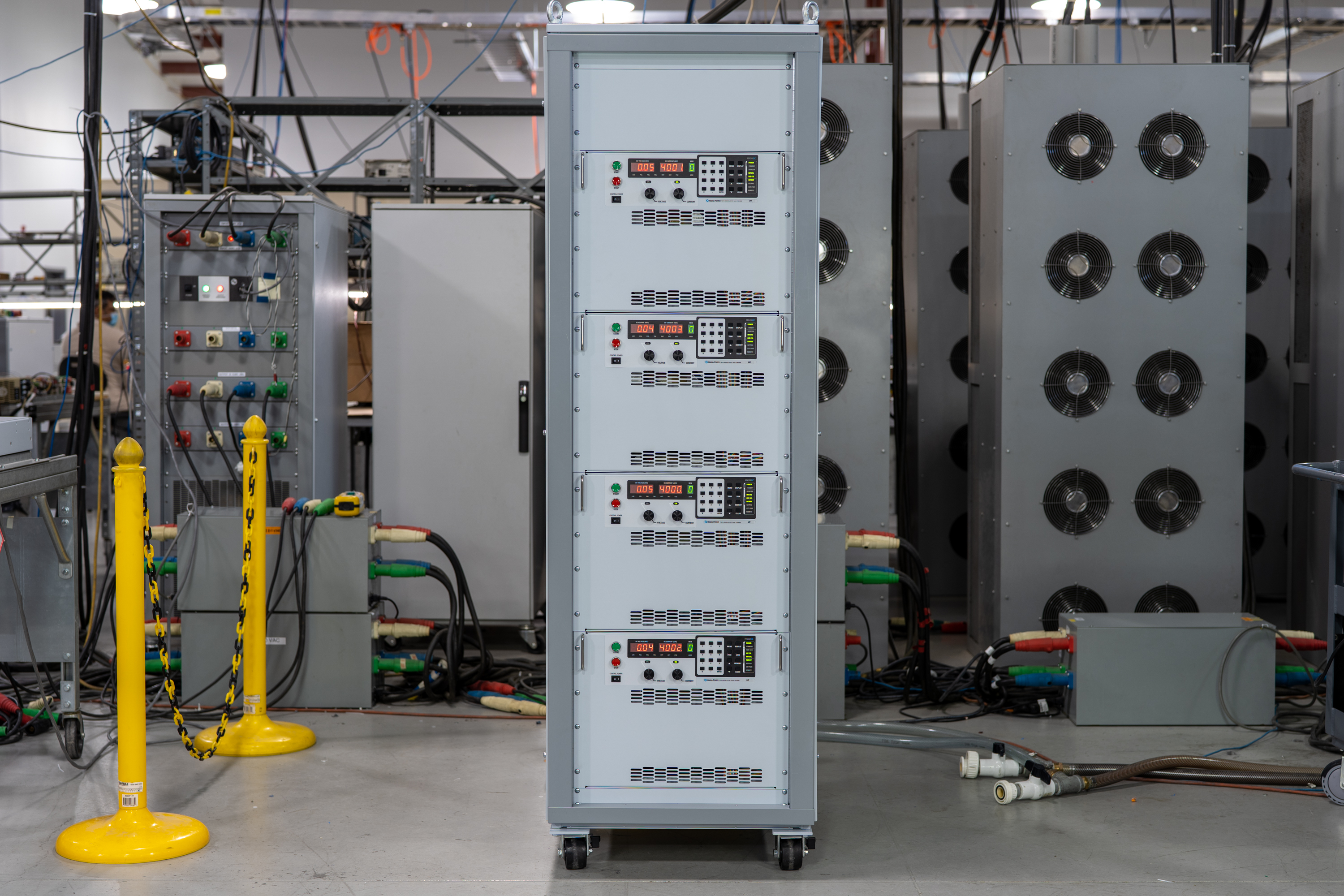
SLX系列以40多年的电源创新为基础,拥有超过26,500多种不同的模型配置,是Magna-Power有史以来最可编程的DC电源系列。 SLX系列提供6个不同功率水平的型号,具有高度颗粒状的电压和电流。凭借行业领先的领先电力密度,坚固的电流式电源处理以及最先进的MagnAlink™分布式DSP数字控制架构,SLX系列符合研发,工业自动化的长期DC功率要求和过程控制应用程序。
主要特点
- 电压,电流和电源控制
- 崎
- 单位控制的16位精度
- SCPI和MODBUS命令集
- 可编程保护功能
- 互锁和硬件紧急停止
- 驱动率控制
- 连续的全功率运行最多可达50°C的环境
- 可配置的模拟数字26针I/O端口
- 数字杂志Magnalink™大师
- 本地,遥控和无铅电压感应
- USB(前后)和RS485接口标准
- 可以,EtherCAT,以太网/IP,LXI TCP/IP以太网,ModbusTCP和Profinet完全集成的通信选项
- 包括Magnactrl软件平台
- 美国制造

Talk with an expert


Do more with MagnaLINK™ distributed digital control.

精密控制与测量
从设定点到负载点,DSP驱动的精密控制。
SLx 系列采用 Magna-Power 的 xGen MagnaLINK™ 数字控制平台,该平台使用分布式 DSP 网络和高速板间通信,利用内部开发的底层通信协议。内部增益调度与现场可调增益相结合,支持广泛的负载条件。
- 电压、电流和功率控制,具有 16 位分辨率。
- 可编程压摆率控制。
- 原生 100 ppm 稳定性。
- 本地、远程和无引线电压检测,实现精确的负载点调节。

即插即用主从控制
通过聚合系统额定值实现无缝功率扩展。
双 MagnaLINK 端口提供新一代数字混合主从控制,单台设备即可指挥同步堆叠系统。通过最多 16 台设备并联扩展电流能力。辅助电流检测连接可向主机实时反馈模拟电流,实现精确的聚合与显示。
- 通过简单的接口接线即可并联多达 16 台设备。
- 单一设定值;同步输出与保护。
- 辅助电流检测反馈,确保精确均流。
- 自动配置和聚合测量,集中显示于单一主机界面。
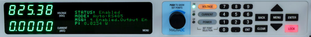
直观、明亮的前面板控制
明亮的显示屏,精细控制,经久耐用。
SLx 系列搭载长寿命混合显示屏——高可见度绿色 V/I 数码管与多行状态/配置屏幕——以及精密耐用的控制装置。黑色阳极氧化机加工铝旋钮可实现精细设定值调节,10 键数字键盘和方向键支持精确的数字输入。专用锁定按钮可保护设置安全,前置 USB 端口使 PC 连接轻松便捷(后面板同样配备 USB 端口)。
- 混合显示屏:明亮的 V/I 数码管 + 多行状态和菜单显示。
- 机加工铝制控制旋钮,实现精细调节。
- 10 键 + 方向键,支持 16 位设定值输入。
- 前面板锁定功能和前置 USB,操作快捷安全。
Rugged by design: safety + reliability, as you'd expect from Magna-Power.
可靠的电流馈电功率处理
坚固耐用的设计:自保护拓扑结构,确保持续运行。
The SLx Series uses a high-frequency, current-fed architecture that adds a control stage beyond conventional voltage-fed designs. This topology inherently limits fault energy—avoiding fast-rising current spikes and magnetic core saturation so the supply self-protects and your load stays safe. Paired with state-of-the-art SiC power semiconductors, SLx delivers class-leading power density, efficiency, and reliability, including continuous full-power operation up to 50°C ambient.
- Current-fed architecture with an added control stage vs. voltage-fed.
- Inherent surge immunity—no current spikes or core saturation.
- Self-protecting behavior under fault conditions.
- SiC devices for high density and efficiency; full power to 50°C.

多层安全保护、联锁与紧急停机
标准可编程限制加硬接线停机保护。
软启动阶段将浪涌电流控制在稳态电流以下,内置诊断功能持续监控线路、温度和内部状态。发生故障时,单次触发(OSHT)保护立即停止逆变器运行。故障信息显示在前面板状态显示屏上,并通过SCPI/Modbus输出,便于快速排查。
- 软启动限制浪涌电流;交流电流保持在满载电流以下。
- 可编程保护:过压、过流、过功率。
- 散热器和输出电容器温度监控。
- 5V联锁输入,支持干接点锁定抑制(控制电源保持供电)。
- 24 V紧急停机绕过逻辑直接切断交流电源;执行完全硬件停机。

目标诊断
LED矩阵映射至内部组件,实现快速现场故障排查。
SLx系列引入了目标诊断功能:每个主要组件的状态LED均映射至后置LED矩阵。技术人员无需拆卸机架和外壳,即可精准定位故障或配置问题。配合MagnaCTRL的EEPROM编辑器,可实现高效的远程支持,确保系统持续运行。
- 后置LED矩阵复现各组件状态LED。
- 产品安装就位且外壳闭合状态下即可诊断故障和配置。
- 配合MagnaCTRL的EEPROM编辑器进行远程检查/更新。
- 缩短故障排查时间,减少停机。
From lab scripts to factory PLCs, flexible programming & integration.
轻松实现软件集成
可读命令,快速响应——兼容任何编程语言。
SLx 系列提供清晰的文本化 API,原生支持 SCPI 和 Modbus。超过 60 条详细文档化的命令涵盖启动/停止、电压/电流/功率设定值、斜率控制、高精度测量及完整配置——助您的脚本和系统从概念验证快速迈向生产部署。
- SCPI 和 Modbus 命令集,行为一致可靠。
- 启动/停止与保护:启用输出、设置跳闸限值、查询状态。
- 高精度读数:电压、电流、功率及检测反馈。
- 面向开发者的文档与示例。
import serial
magnaPower = serial.Serial(port='COM4', baudrate=115200)
magnaPower.write('*IDN?\n'.encode())
print magna_power.readline()
magnaPower.write('VOLT 0\n'.encode())
magnaPower.write('CURR 0\n'.encode())
magnaPower.write('OUTP:START\n'.encode())
magnaPower.write('VOLT 270\n'.encode())
currSetPoints = [50, 100, 150, 250]
for currSetPoint in currSetPoints:
    print 'Setting Current to %s A' % currSetPoint
    magnaPower.write('CURR {0}\n'.format(currSetPoint).encode())
    magnaPower.write('MEAS:VOLT?\n'.encode())
    print magnaPower.readline()
    time.sleep(20)
magnaPower.write('OUTP:STOP\n'.encode())
magnaPower.close()
magna_power = serial('COM4', 'BaudRate', 115200);
fopen(magnaPower);
fprintf(magnaPower,'*IDN?');
idn = fscanf(magnaPower);
fprintf(magnaPower,'VOLT 0');
fprintf(magnaPower,'CURR 0');
fprintf(magnaPower,'OUTP:START');
fprintf(magnaPower,'VOLT 270');
for currSetPoint in [50, 100, 150, 250]
    display('Setting Current to '+currSetPoint+' A');
    fprintf(magnaPower, 'CURR '+currSetPoint);
    fprintf(magnaPower,'MEAS:VOLT?');
    display(fscanf(magnaPower));
    pause(20);
end
#include <stdio.h>
#include <stdint.h>
#include <string.h>
#include <windows.h>

int main()
{
    printf("Opening connection.\n");

    uint8_t recvBuffer[sizeof(uint8_t) * 256];
    memset(recvBuffer, 0, 256);

    // Choose the serial port name.
    // COM ports higher than COM9 need the \\.\ prefix, which is written as
    // "\\\\.\\" in C because we need to escape the backslashes.
    const char* device = "\\\\.\\COM4";

    // Choose the baud rate (bits per second).
    uint32_t baud_rate = 115200;

    HANDLE port = open_serial_port(device, baud_rate);
    if (port == INVALID_HANDLE_VALUE) { return 1; }

    char* scpiCmd = (char*)"*IDN?\n";
    size_t cmdLen = strlen(scpiCmd);
    int result = write_port(port, (uint8_t*)scpiCmd, cmdLen);
    if (result < 0)
        return -1;

    result = read_port(port, recvBuffer, 256);
    printf("Sent: %s\nReceived: %s\n", scpiCmd, recvBuffer);

    scpiCmd = (char*)"VOLT 0\n";
    cmdLen = strlen(scpiCmd);
    result = write_port(port, (uint8_t*)scpiCmd, cmdLen);
    if (result < 0)
        return -1;

    scpiCmd = (char*)"CURR 0\n";
    cmdLen = strlen(scpiCmd);
    result = write_port(port, (uint8_t*)scpiCmd, cmdLen);
    if (result < 0)
        return -1;

    scpiCmd = (char*)"OUTP:START\n";
    cmdLen = strlen(scpiCmd);
    result = write_port(port, (uint8_t*)scpiCmd, cmdLen);
    if (result < 0)
        return -1;

    scpiCmd = (char*)"VOLT 270\n";
    cmdLen = strlen(scpiCmd);
    result = write_port(port, (uint8_t*)scpiCmd, cmdLen);
    if (result < 0)
        return -1;

    char setPoints[4][5] = {"50", "100", "150", "200"};
    char setPointBuffer[40];
    scpiCmd = (char*)"MEAS:VOLT?\n";

    for (int i = 0; i < 4; i++)
    {
        sprintf(setPointBuffer, "CURR %s\n", setPoints[i]);
        printf("Setting current to %s A\n", setPoints[i]);
        cmdLen = strlen(setPointBuffer);
        result = write_port(port, (uint8_t*)setPointBuffer, cmdLen);
        if (result < 0)
            return -1;
        memset(recvBuffer, 0, 256);
        result = read_port(port, recvBuffer, 256);
        printf("Received: %s\n", recvBuffer);
        Sleep(20000);  // 20000ms = 20s
    }

    scpiCmd = (char*)"OUTP:STOP\n";
    cmdLen = strlen(scpiCmd);
    result = write_port(port, (uint8_t*)scpiCmd, cmdLen);
    if (result < 0)
        return -1;

    CloseHandle(port);

    printf("Connection closed.\n");
    return 0;
}
using System;
using System.IO.Ports;
using System.Threading;

namespace SerialCommunicationInCSharp
{
  public class Program
  {
    static bool _continue;
    static SerialPort serialPort;

    public static void Main(string[] args)
    {
      Thread readThread = new Thread(Read);

      Console.WriteLine("Opening connection.");

      // Create a new SerialPort object with default settings.
      serialPort = new SerialPort("COM4", 115200, Parity.None, 8, StopBits.One);

      // Set the read/write timeouts
      serialPort.ReadTimeout = 500;
      serialPort.WriteTimeout = 500;

      serialPort.Open();
      _continue = true;
      readThread.Start();

      Console.WriteLine("Sending: *IDN?");
      serialPort.WriteLine("*IDN?");

      serialPort.WriteLine("VOLT 0");
      serialPort.WriteLine("CURR 0");
      serialPort.WriteLine("OUTP:START");
      serialPort.WriteLine("VOLT 270");

      string[] currSetPoints = { "50", "100", "150", "250" };
ß
      for(int i = 0; i < currSetPoints.Length; i++)
      {
        serialPort.WriteLine(String.Format("'CURR {0}", currSetPoints[i]));
        serialPort.WriteLine("MEAS:VOLT?");
        Thread.Sleep(20000);
      }

      serialPort.WriteLine("OUTP:STOP");

      Console.WriteLine("Closing connection.");
      _continue = false;
      serialPort.Close();
      }

    public static void Read()
    {
      while (_continue)
      {
        try
        {
          string message = serialPort.ReadLine();
          Console.WriteLine("Received: " + message);
        }
        catch (TimeoutException) { }
      }
    }
  }
}

外部用户I/O
灵活的隔离式模拟-数字控制。
所有SLx系列电源均标配一个26针D-Sub连接器,指定为外部用户I/O。该连接器提供:
- 8路数字输出(5V逻辑)
- 4路数字输入(5V逻辑)
- 4路模拟输出(0-10V逻辑)
- 4路模拟输入(0-10V逻辑)
外部用户I/O与输出端子隔离,并以接地为参考。连接器引脚可由用户配置,允许用户选择其应用所需的功能,同时为未来新功能提供扩展能力。使用数字输出可将电源与外部使能信号或数字故障监测逻辑等集成,或使用0-10V模拟输出监测电压和电流。还提供了一个专用高速模拟输入,采样率为2 kHz,可实现近实时控制。
工业通信与控制
从实验室网络到PLC——按您的方式集成。
该系列出厂即配备双USB(前置和后置)和RS485接口,支持SCPI和Modbus协议。针对网络和工厂自动化需求,可选择完全集成的选项,支持Modbus,提供详尽的文档,并附带设备描述文件,以加速PLC设置和标签映射。
- 标配双USB(前置+后置)和RS485。
- 通过LXI TCP/IP以太网(+LXI)选项实现TCP/IP网络连接。
- PLC现场总线选项:CANopen(+CAN)、EtherCAT(+ECAT)、EtherNet/IP(+EIP)、Modbus-TCP(+MTCP)、PROFINET(+PROF)。
- 包含设备文件:EDS(CANopen/EtherNet/IP)、ESI XML(EtherCAT)、GSDML(PROFINET),实现快速PLC集成。
- 完整的命令文档、示例和诊断工具。
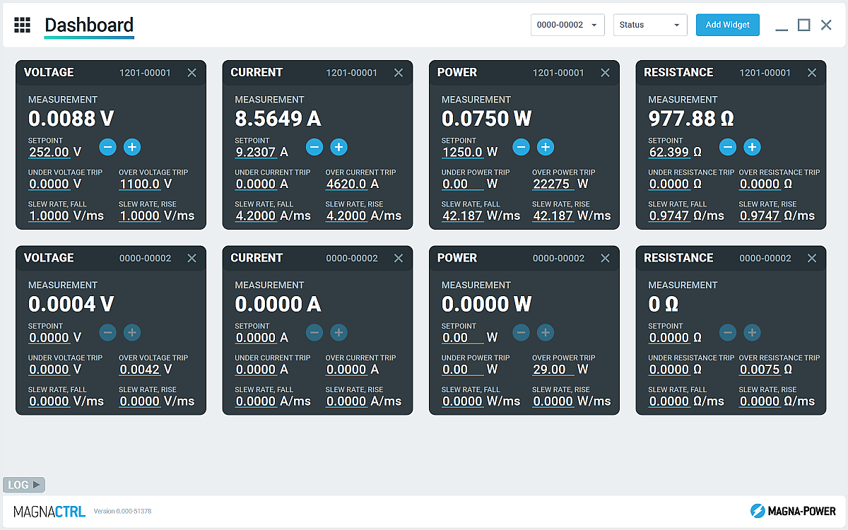
内置 MagnaCTRL 软件
多产品仪表板控制、诊断和更新——开箱即用。
MagnaCTRL 是一款现代化的多产品控制平台,随 xGen 产品附带提供。构建仪表板、配置 I/O、运行更新以及访问深度诊断功能——一切尽在一个应用中。
- 可配置仪表板:添加/排列小组件,监控和控制多台已连接设备。
- 产品浏览器:自动检测设备、保存连接,并在后续会话中自动重连。
- 外部用户 I/O 面板:映射 26 针 I/O,导出/导入引脚映射,实现快速部署。
- 固件/软件更新:自动检测新版本发布;如需要,可离线执行手动更新(请参阅更新日志)
- 校准工具:调整编程/测量增益/偏移量;在指引下,调谐控制回路增益。
- 数据记录:图形化输出及 .csv 格式记录电压、电流和功率的测量值与设定值随时间的变化
State-of-the-art USA manufacturing with worldwide support

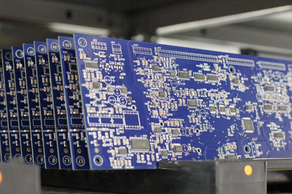
美国制造
垂直整合制造,实现全面质量管控。
Magna-Power 产品的设计、制造、测试和售后服务均在位于新泽西州弗莱明顿的 Magna-Power 总部完成,总部面积达 73,500 平方英尺。金属加工、磁性元件制造、PCB 组装和老化测试均在内部完成,从而严格把控质量、成本和交货周期。
- 美国制造:工程设计、生产制造和售后服务集于一处。
- 内部生产:金属加工、磁性元件、SMT PCB 和表面处理。
- 可靠性验证:每台设备均经过全面测试、校准和老化试验。
全球服务与OEM零部件支持
工厂级专业技术,本地化响应。
Magna-Power以工厂及授权服务中心为其产品提供全面支持,服务网络覆盖北美、欧洲、英国、亚太、东亚及南美地区。无论是否在保修期内,均采用工厂标准流程和原厂零部件,将设备恢复至出厂规格。
- 全球覆盖:总部位于新泽西州,并设有多个区域授权服务中心。
- 一致的维修标准:采用工厂诊断流程、作业指导书和系统图纸。
- 原厂OEM零部件:经过测试的替换组件,确保可靠、高效的维修服务,最大限度减少停机时间。
Model Ordering Guide
For both ordering and production, SLX系列 models are uniquely defined by several key characteristics, as defined by the following diagram:

SLX系列 Models
There are 171 different models in the SLX系列 spanning power levels: 1.5 kW, 2.6 kW, 4 kW, 6 kW, 8 kW, 10 kW. To determine the appropriate model:
- Select the desired Max Voltage (Vdc) from the left-most column.
- Select the desired Max Current (Adc) from the same row that contains your desired Max Voltage.
- Construct your model number according to the model ordering guide.
| Max Voltage Vdc |
1.5 kW | 2.6 kW | 4 kW | 6 kW | 8 kW | 10 kW | Ripple mVrms |
Efficiency |
|---|---|---|---|---|---|---|---|---|
| Max Current Adc | ||||||||
| 5 | 250 | — | — | — | — | — | 30 | 84% |
| 10 | 150 | 250 | — | — | — | — | 30 | 89% |
| 16 | 93 | 162 | 250 | — | — | — | 40 | 89% |
| 20 | 75 | 130 | 200 | 250 | — | — | 40 | 90% |
| 25 | 60 | 104 | 160 | 240 | — | — | 50 | 91% |
| 32 | 46 | 81 | 125 | 186 | 250 | — | 60 | 91% |
| 40 | 37 | 65 | 100 | 150 | 200 | 250 | 80 | 91% |
| 50 | 30 | 52 | 80 | 120 | 160 | 200 | 70 | 92% |
| 60 | 25 | 43 | 66 | 100 | 133 | 166 | 100 | 93% |
| 80 | 18 | 32 | 50 | 75 | 100 | 125 | 120 | 93% |
| 100 | 15 | 26 | 40 | 60 | 80 | 100 | 120 | 93% |
| 125 | 12 | 20 | 32 | 48 | 64 | 80 | 110 | 93% |
| 160 | 9 | 16 | 25 | 36 | 50 | 60 | 110 | 93% |
| 200 | 7.5 | 13 | 20 | 30 | 40 | 50 | 110 | 94% |
| 250 | 6 | 10.4 | 16 | 24 | 32 | 40 | 110 | 94% |
| 300 | 5 | 8.6 | 13.2 | 20 | 26.4 | 33.3 | 160 | 94% |
| 375 | 4 | 6.9 | 10.4 | 16 | 21.3 | 26.5 | 160 | 94% |
| 400 | 3.7 | 6.5 | 10 | 15 | 20 | 25 | 170 | 95% |
| 500 | 3 | 5.2 | 8 | 12 | 16 | 20 | 250 | 95% |
| 600 | 2.5 | 4.3 | 6.4 | 10 | 13.3 | 16.5 | 250 | 95% |
| 800 | 1.8 | 3.2 | 5 | 7.5 | 10 | 12.5 | 350 | 95% |
| 1000 | 1.5 | 2.6 | 4 | 6 | 8 | 10 | 400 | 95% |
| 1250 | 1.2 | 2 | 3.2 | 4.8 | 6.4 | 8 | 700 | 95% |
| 1500 | 1 | 1.7 | 2.6 | 4 | 5.3 | 6.6 | 1000 | 95% |
| 2000 | 0.75 | 1.3 | 2 | 3 | 4 | 5 | 6500 | 95% |
| 2500 | 0.6 | 1 | 1.6 | 2.4 | 3.2 | 4 | 7500 | 95% |
| 3000 | 0.5 | 0.86 | 1.3 | 2 | 2.6 | 3.3 | 8500 | 95% |
| AC Input Voltage Vac |
Input Current Per Phase Aac | |||||||
| UI (100-240 Vac, 1Φ) | 18 - 81 | — | — | — | — | — | ||
| UI2 (208-240 Vac, 1Φ) | — | 15 - 13 | — | — | — | — | ||
| 208/240 Vac, 3Φ | 6 | 9 | 14 | 20 | 27 | 33 | ||
| 380/415 Vac, 3Φ | 4 | 6 | 9 | 12 | 17 | 19 | ||
| 440/480 Vac, 3Φ | 3 | 5 | 7 | 10 | 14 | 16 | ||
1 15 Aac input current at 120 Vac, 1Φ
Specifications are subject to change without notice. Unless otherwise noted, all specifications measured at the product's maximum ratings.
AC Input Specifications
UI2, 208-240 Vac, 1-phase
208 Vac, 3-phase
240 Vac, 3-phase
380/400 Vac, 3-phase
415 Vac, 3-phase
440 Vac, 3-phase
480 Vac 3-phase
> 0.92, 3-phase AC inputs
DC Output Specifications
Current control: ± 0.03% of rated current
Power control: ± 0.05% of rated power
Current control: ± 0.06% of rated current
Power control: ± 0.08% of rated power
Current control: ± 0.075% of rated current
Current control: 0.04%/ºC of rated current
Power control: 0.04%/ºC of rated power
Maximum (Fastest): Rated voltage x 0.006 [V/ms]
Maximum (Fastest): Rated current x 0.005 [A/ms]
Maximum (Fastest): Rated power x 0.0025 [W/ms]
Programming Specifications
Current: ± 0.06% of rated current
Power: ± 0.10% of rated power
Current: ± 0.08% of rated current
Power: ± 0.10% of rated power
Current: ± 0.08% of rated current
Power: ± 0.10% of rated power
Current: ± 0.80% of rated current
Power: ± 1.20% of rated power
Current: ± 0.08% of rated current
Power: ± 0.10% of rated power
Programming Voltage: 0-10 V
Monitoring Voltage: 0-10 V, 3 mA capacity
Monitoring Impedance: 0.005 Ω
Reference Voltage: 10 V, 20 mA capacity
Interface Specifications
USB Host (Rear): Type B
RS485 (Rear): RJ-45
MagnaLINK™: RJ-25 x 2
Referenced to ground; isolated from the DC output
See User Manual for pin layout
EtherCAT (+ECAT): RJ-45 x 2
EtherNet/IP (+EIP): RJ-45 x 2
LXI TCP/IP Ethernet (+LXI): RJ-45
ModbusTCP (+MTCP): RJ-45 x 2
PROFINET (+PROF): RJ-45 x 2
Physical Specifications
1.75” H x 19” W x 24” D (4.4 x 48.3 x 61.0 cm)
2.6 kW models: 34 lbs (15.42 kg)
4 kW models: 35 lbs (15.88 kg)
6 kW models: 35 lbs (15.88 kg)
8 kW models: 36 lbs (16.33 kg)
10 kW models: 36 lbs (16.33 kg)
Environmental Specifications
Regulatory Specifications
CISPR 22 / EN 55022 Class A
The following are vectorized diagrams for the SLX系列. Refer to the Downloads section for downloadable drawings.


Integrated Options
Standard integrated options are available for Magna-Power products, allowing the product's performance and communication interfaces to be tailors to the specific application.
- Option
- +FP1
- Option
- +CAN
- Option
- +ECAT
- Option
- +EIP
- Option
- +LXI

- Option
- +MTCP
- Option
- +PROF
Accessories
External accessories and integration services available for this product.