ML系列
Programmable DC Power Supply
- Size
- Power
- 500 kW to 10 MW+
- Manufactured
- USA
- Build-time
- 16-20 weeks
Magna-Power Electronics的ML系列从头开始设计,旨在设定功率密度和性能的新标准。利用先进的水冷技术,500 kW和1,000 kW ML系列型号的功率密度比Magna-Power的其他空气冷却型号增加了近四倍。通过在主从并联配置中连接,ML系列可以达到超过10 MW的功率水平。基于Magna-Power标志性的可靠电流馈电功率处理拓扑和创新的谐波中和技术,ML系列电源提供可靠且高效的电能转换,具有低谐波失真。这些电源在新泽西州Flemington设计和制造,体现了Magna-Power对质量、可靠性和先进工程的承诺。
主要特点
- 500 kW和1,000 kW型号;可扩展至10 MW
- 12位精度控制
- 使用SCPI命令进行远程编程
- 可编程保护功能
- 用于外部紧急停止的安全联锁
- LabVIEW驱动程序
- 环境温度高达50°C的连续全功率操作
- 37针模拟-数字用户I/O端口
- 集成电磁阀用于冷凝控制
- 高性能主从控制
- 本地、远程和无引线电压感应
- 提供标准RS232和LAN TCP/IP以太网通信选项
- 包括RIS Panel软件平台
- 美国制造

Talk with an expert


High power density, water cooled megawatt-scale DC power systems
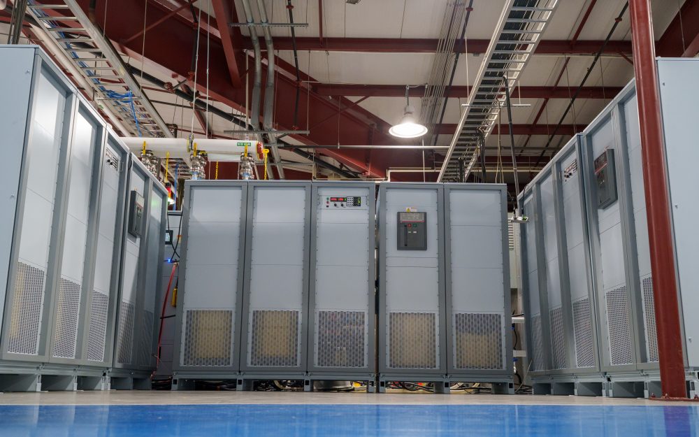
高密度水冷性能
从 500 kW 到 10 MW+ 的清洁、精确输出。
ML 系列可编程 DC 电源利用先进的水冷冷板和内部歧管,在每个机柜中实现 500 kW 和 1,000 kW 的输出功率,效率高达 96%,功率密度比同类风冷机型高出近四倍,且在 50°C 环境温度下仍可满额定功率运行。ML 系列基于 MagnaDC 的电流馈电拓扑结构,提供 12 位(0.025%)编程分辨率、严格的线路/负载调节,以及 ±0.075% 的电压和电流编程精度和低纹波——为多兆瓦级测试和工艺系统带来实验室级性能。

无级前面板控制,可选空白面板
需要操控时触手可及,无需时隐于无形。
The standard SL front panel provides rotary and key-based control, bright digital metering, and clear status indicators, so operators can configure setpoints, start and stop the supply, and see system health at a glance. For OEMs and production tools, the optional blank (C-version) front panel removes local controls altogether while retaining full control via communication interfaces and rear 37-pin user I/O, keeping systems secure, clean, and operator-proof.
按需配置,集成选项
丰富的标准功能,按需扩展。
Like the rest of the MagnaDC line, MT Series supplies start with a strong control base: SCPI over RS232, isolated rear User I/O, LabVIEW and IVI drivers, and Remote Interface Software included. From there, integrated options let you tailor each system for its role—High Isolation Output (+ISO) for extended series stacking, High Slew Rate Output (+HS) for faster dynamics, LXI TCP/IP Ethernet (+LXI) and IEEE-488 GPIB (+GPIB) for additional communications, plus protection and mechanical options such as an Integrated Blocking Diode (+BD) and Pedestal Base (+PB) for fixed installations.
谐波中和器,打造更纯净的大功率系统
从源头降低THD,更轻松地满足电能质量合规要求。
输入电流谐波是三相整流器的固有副产物:标准6脉波前端会在基波的1、5、7、11、13……倍频处产生谐波电流,其中仅5次和7次谐波分量就分别约占基波的20%和14%。这些电流可能激励敏感负载(如带有串联电容器/电感器的照明镇流器),并使满足IEEE 519等电能质量标准变得更加困难。减少谐波问题最可靠的方法是从源头消除谐波电流。
针对大功率系统,Magna-Power制造了特殊绕制的谐波中和器,可增加输入相数并以无源方式大幅降低输入电流THD。标准1.5–150 kW的Magna-Power电源采用6脉波波形,而250 kW MT Series和500 kW ML Series型号内置12脉波谐波中和器,1000 kW ML Series型号内置24脉波谐波中和器——对用户完全透明。

Rugged by design: safety + reliability, as you'd expect from Magna-Power.

可靠的电流馈电功率处理
坚固耐用的设计:自保护拓扑结构,确保持续运行。
The SLx Series uses a high-frequency, current-fed architecture that adds a control stage beyond conventional voltage-fed designs. This topology inherently limits fault energy—avoiding fast-rising current spikes and magnetic core saturation so the supply self-protects and your load stays safe. Paired with state-of-the-art SiC power semiconductors, SLx delivers class-leading power density, efficiency, and reliability, including continuous full-power operation up to 50°C ambient.
- Current-fed architecture with an added control stage vs. voltage-fed.
- Inherent surge immunity—no current spikes or core saturation.
- Self-protecting behavior under fault conditions.
- SiC devices for high density and efficiency; full power to 50°C.
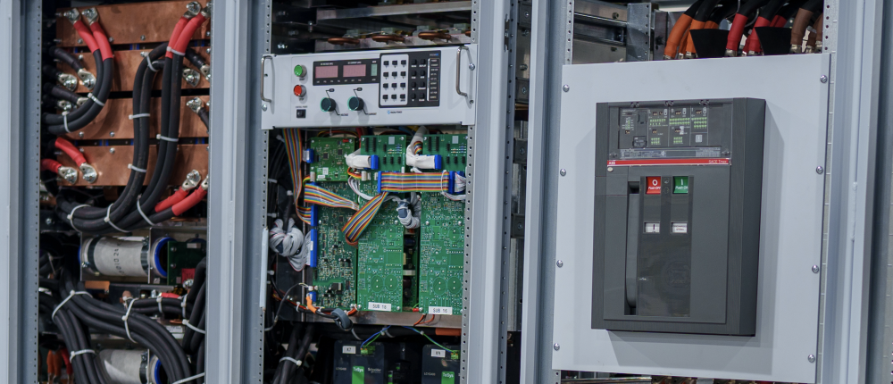
安全功能与互锁
软启动、可编程保护以及机械线路断开装置,提供真正的安全保障。
MagnaDC supplies start gently and watch continuously. A soft-start stage keeps inrush below steady-state draw, while built-in diagnostics monitor line, thermal, and control conditions. In standby or on a diagnostic fault, an embedded AC contactor mechanically disconnects the mains, assuring the unit only processes power when intended. Faults are shown on the front-panel status display, through 5V digital outputs, and are queryable via SCPI.
-
Programmable trips: Over voltage (OVT) and over current (OCT)/
-
Control integrity: Program-line over-voltage detection.
-
Thermal protection: Over temperature on internal heatsinks.
-
Interlock/E-stop fault monitoring as a standard diagnostic.
-
Field integration: 5V interlock input (with 5V reference) for a dry-contact, latching inhibit with control power maintained.
From lab scripts to factory PLCs, flexible programming & integration.
轻松实现软件集成
可读命令,快速响应——兼容任何编程语言。
MagnaDC 电源提供清晰的文本API接口,支持原生SCPI——一种通过套接字通信发送的ASCII命令语言。超过40条详细文档化的命令涵盖启动/停止、电压和电流设定值、高精度测量以及完整配置——让您的脚本和系统从概念验证快速迈向生产部署。
- SCPI命令集,行为一致可靠。
- 启动/停止与保护功能:启用输出、设置跳闸限值、查询状态。
- 高精度读取:电压、电流、功率及检测反馈。
- 面向开发者的文档与示例。
import serial
magnaPower = serial.Serial(port='COM4', baudrate=19200)
magnaPower.write('*IDN?\n'.encode())
print magna_power.readline()
magnaPower.write('VOLT 0\n'.encode())
magnaPower.write('CURR 0\n'.encode())
magnaPower.write('OUTP:START\n'.encode())
magnaPower.write('VOLT 270\n'.encode())
currSetPoints = [50, 100, 150, 250]
for currSetPoint in currSetPoints:
    print 'Setting Current to %s A' % currSetPoint
    magnaPower.write('CURR {0}\n'.format(currSetPoint).encode())
    magnaPower.write('MEAS:VOLT?\n'.encode())
    print magnaPower.readline()
    time.sleep(20)
magnaPower.write('OUTP:STOP\n'.encode())
magnaPower.close()
magna_power = serial('COM4', 'BaudRate', 19200);
fopen(magnaPower);
fprintf(magnaPower,'*IDN?');
idn = fscanf(magnaPower);
fprintf(magnaPower,'VOLT 0');
fprintf(magnaPower,'CURR 0');
fprintf(magnaPower,'OUTP:START');
fprintf(magnaPower,'VOLT 270');
for currSetPoint in [50, 100, 150, 250]
    display('Setting Current to '+currSetPoint+' A');
    fprintf(magnaPower, 'CURR '+currSetPoint);
    fprintf(magnaPower,'MEAS:VOLT?');
    display(fscanf(magnaPower));
    pause(20);
end
#include <stdio.h>
#include <stdint.h>
#include <string.h>
#include <windows.h>

int main()
{
    printf("Opening connection.\n");

    uint8_t recvBuffer[sizeof(uint8_t) * 256];
    memset(recvBuffer, 0, 256);

    // Choose the serial port name.
    // COM ports higher than COM9 need the \\.\ prefix, which is written as
    // "\\\\.\\" in C because we need to escape the backslashes.
    const char* device = "\\\\.\\COM4";

    // Choose the baud rate (bits per second).
    uint32_t baud_rate = 19200;

    HANDLE port = open_serial_port(device, baud_rate);
    if (port == INVALID_HANDLE_VALUE) { return 1; }

    char* scpiCmd = (char*)"*IDN?\n";
    size_t cmdLen = strlen(scpiCmd);
    int result = write_port(port, (uint8_t*)scpiCmd, cmdLen);
    if (result < 0)
        return -1;

    result = read_port(port, recvBuffer, 256);
    printf("Sent: %s\nReceived: %s\n", scpiCmd, recvBuffer);

    scpiCmd = (char*)"VOLT 0\n";
    cmdLen = strlen(scpiCmd);
    result = write_port(port, (uint8_t*)scpiCmd, cmdLen);
    if (result < 0)
        return -1;

    scpiCmd = (char*)"CURR 0\n";
    cmdLen = strlen(scpiCmd);
    result = write_port(port, (uint8_t*)scpiCmd, cmdLen);
    if (result < 0)
        return -1;

    scpiCmd = (char*)"OUTP:START\n";
    cmdLen = strlen(scpiCmd);
    result = write_port(port, (uint8_t*)scpiCmd, cmdLen);
    if (result < 0)
        return -1;

    scpiCmd = (char*)"VOLT 270\n";
    cmdLen = strlen(scpiCmd);
    result = write_port(port, (uint8_t*)scpiCmd, cmdLen);
    if (result < 0)
        return -1;

    char setPoints[4][5] = {"50", "100", "150", "200"};
    char setPointBuffer[40];
    scpiCmd = (char*)"MEAS:VOLT?\n";

    for (int i = 0; i < 4; i++)
    {
        sprintf(setPointBuffer, "CURR %s\n", setPoints[i]);
        printf("Setting current to %s A\n", setPoints[i]);
        cmdLen = strlen(setPointBuffer);
        result = write_port(port, (uint8_t*)setPointBuffer, cmdLen);
        if (result < 0)
            return -1;
        memset(recvBuffer, 0, 256);
        result = read_port(port, recvBuffer, 256);
        printf("Received: %s\n", recvBuffer);
        Sleep(20000);  // 20000ms = 20s
    }

    scpiCmd = (char*)"OUTP:STOP\n";
    cmdLen = strlen(scpiCmd);
    result = write_port(port, (uint8_t*)scpiCmd, cmdLen);
    if (result < 0)
        return -1;

    CloseHandle(port);

    printf("Connection closed.\n");
    return 0;
}
using System;
using System.IO.Ports;
using System.Threading;

namespace SerialCommunicationInCSharp
{
  public class Program
  {
    static bool _continue;
    static SerialPort serialPort;

    public static void Main(string[] args)
    {
      Thread readThread = new Thread(Read);

      Console.WriteLine("Opening connection.");

      // Create a new SerialPort object with default settings.
      serialPort = new SerialPort("COM4", 19200, Parity.None, 8, StopBits.One);

      // Set the read/write timeouts
      serialPort.ReadTimeout = 500;
      serialPort.WriteTimeout = 500;

      serialPort.Open();
      _continue = true;
      readThread.Start();

      Console.WriteLine("Sending: *IDN?");
      serialPort.WriteLine("*IDN?");

      serialPort.WriteLine("VOLT 0");
      serialPort.WriteLine("CURR 0");
      serialPort.WriteLine("OUTP:START");
      serialPort.WriteLine("VOLT 270");

      string[] currSetPoints = { "50", "100", "150", "250" };
ß
      for(int i = 0; i < currSetPoints.Length; i++)
      {
        serialPort.WriteLine(String.Format("'CURR {0}", currSetPoints[i]));
        serialPort.WriteLine("MEAS:VOLT?");
        Thread.Sleep(20000);
      }

      serialPort.WriteLine("OUTP:STOP");

      Console.WriteLine("Closing connection.");
      _continue = false;
      serialPort.Close();
      }

    public static void Read()
    {
      while (_continue)
      {
        try
        {
          string message = serialPort.ReadLine();
          Console.WriteLine("Received: " + message);
        }
        catch (TimeoutException) { }
      }
    }
  }
}

用于PLC控制或PHIL仿真的外部用户 I/O
像I/O模块一样接线——无需额外隔离。
Via the included rear 37-pin User I/O connector, MagnaDC supplies can be fully driven and monitored by external signals or a PLC. Voltage, current, OVT, and OCT set points are programmed with 0–10 V analog inputs, while each diagnostic condition has its own +5V digital status pin. Built-in +2.5V, +5V, and +10V reference rails let you use dry contacts without adding external supplies. All I/O is isolated from the output and referenced to earth ground as standard.
-
0–10 V analog programming for V, I, OVT, and OCT.
-
Per-fault digital outputs: each diagnostic has its own +5V pin.
-
Isolated user I/O referenced to earth ground—no extra isolators.
-
With High Slew Rate Output (+HS), high-bandwidth response and fast rise times support HIL/PHIL simulation applications.
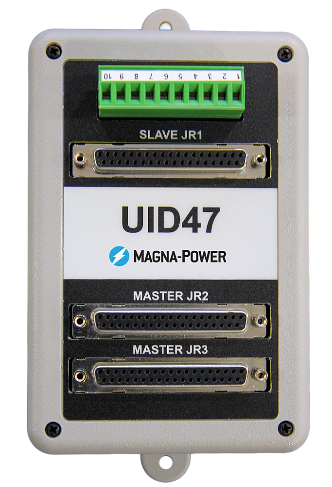
高性能主从操作
在不牺牲性能的前提下扩展电压或电流。
All MagnaDC supplies support master-slave operation, using gate-drive signals from the master when configured for parallel, so the whole stack behaves like a single supply—with one control loop and no noisy long analog references. The optional UID47 accessory simplifies wiring for series or parallel sets with near-equal sharing.
-
Single control loop parallel operation: Master gate-drive to slaves for consistent dynamics.
-
Plug & play with the UID47, enabling parallel or series stacks with current/voltage sharing.
-
Series up to the DC isolation rating without added hardware.
No additional ORing diodes required for parallel operation.
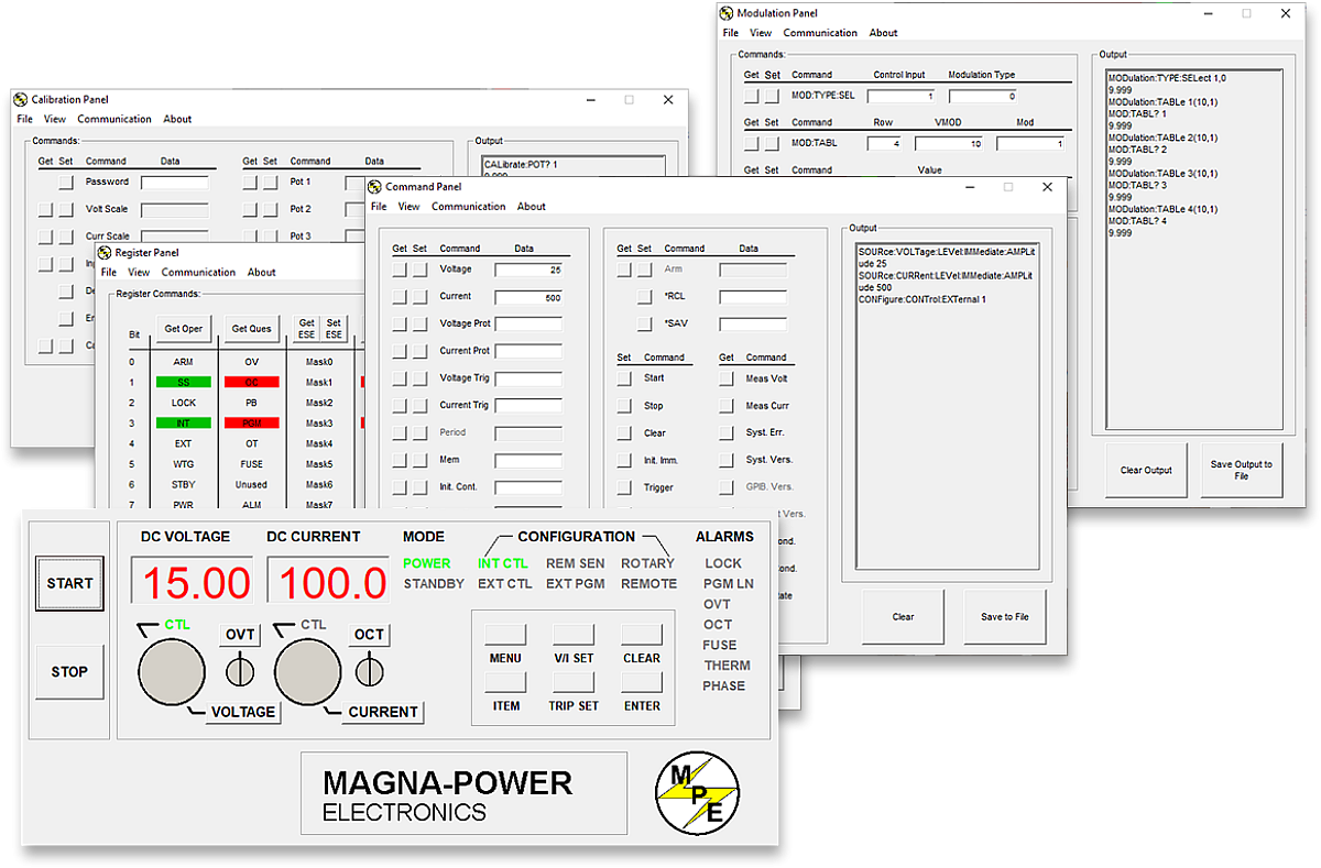
Magna-Power 软件、LabVIEW 和 IVI 驱动程序
从虚拟前面板到全自动化——开箱即用。
每台 MagnaDC 电源均包含 IVI 驱动程序和 NI LabVIEW 驱动程序,提供完整的 VI 集以及示例程序,让您在几分钟内即可与硬件通信。如需通过 PC 进行直接的前面板式控制,Magna-Power 远程接口软件可提供电源的全面视图——从命令和寄存器到校准和固件。
-
随附 IVI 和 NI LabVIEW 驱动程序及完整 VI 集。
-
示例程序助您快速启动集成和测试。
-
远程接口软件包含:
-
虚拟前面板,用于手动控制
-
命令面板,用于浏览和发送命令
-
寄存器面板,用于实时状态监控
-
校准面板,用于内部数字电位器
-
固件面板,用于就地升级
-
调制面板,用于模拟非线性曲线
-
-
所有通信接口在软件和驱动程序中均受支持,提供一致的编程体验。
State-of-the-art USA manufacturing with worldwide support

美国制造
垂直整合制造,实现全面质量管控。
Magna-Power 产品的设计、制造、测试和售后服务均在位于新泽西州弗莱明顿的 Magna-Power 总部完成,总部面积达 73,500 平方英尺。金属加工、磁性元件制造、PCB 组装和老化测试均在内部完成,从而严格把控质量、成本和交货周期。
- 美国制造:工程设计、生产制造和售后服务集于一处。
- 内部生产:金属加工、磁性元件、SMT PCB 和表面处理。
- 可靠性验证:每台设备均经过全面测试、校准和老化试验。
全球服务与OEM零部件支持
工厂级专业技术,本地化响应。
Magna-Power以工厂及授权服务中心为其产品提供全面支持,服务网络覆盖北美、欧洲、英国、亚太、东亚及南美地区。无论是否在保修期内,均采用工厂标准流程和原厂零部件,将设备恢复至出厂规格。
- 全球覆盖:总部位于新泽西州,并设有多个区域授权服务中心。
- 一致的维修标准:采用工厂诊断流程、作业指导书和系统图纸。
- 原厂OEM零部件:经过测试的替换组件,确保可靠、高效的维修服务,最大限度减少停机时间。
Model Ordering Guide
For both ordering and production, ML系列 models are uniquely defined by several key characteristics, as defined by the following diagram:

ML系列 Models
There are 38 different models in the ML系列 spanning power levels: 500 kW and 1000 kW. To determine the appropriate model:
- Select the desired Max Voltage (Vdc) from the left-most column.
- Select the desired Max Current (Adc) from the same row that contains your desired Max Voltage.
- Construct your model number according to the model ordering guide.
| Max Voltage Vdc |
500 kW | 1000 kW | Ripple mVrms |
Efficiency |
|---|---|---|---|---|
| Max Current Adc | ||||
| 100 | 5000 | — | 100 | 91% |
| 125 | 4000 | — | 100 | 91% |
| 160 | 3125 | — | 120 | 92% |
| 200 | 2500 | 5000 | 125 | 92% |
| 250 | 2000 | 4000 | 130 | 92% |
| 300 | 1666 | 3333 | 160 | 93% |
| 375 | 1333 | 2666 | 170 | 93% |
| 400 | 1250 | 2500 | 180 | 95% |
| 500 | 1000 | 2000 | 220 | 95% |
| 600 | 833 | 1666 | 300 | 95% |
| 800 | 625 | 1250 | 400 | 96% |
| 1000 | 500 | 1000 | 500 | 96% |
| 1250 | 400 | 800 | 500 | 96% |
| 1600 | 312 | 625 | 600 | 96% |
| 2000 | 250 | 500 | 800 | 96% |
| 2500 | 200 | 400 | 900 | 96% |
| 3000 | 166 | 333 | 1000 | 96% |
| 4000 | 125 | 250 | 1100 | 96% |
| 5000 | 100 | 200 | 1500 | 96% |
| 6000 | 83 | 166.6 | 2000 | 96% |
Specifications are subject to change without notice. Unless otherwise noted, all specifications measured at the product's maximum ratings.
AC Input Specifications
480 Vac, 3-phase
DC Output Specifications
Current control: ± 0.03% of rated current
Current control: ± 0.06% of rated current
Current control: 0.06%/ºC of rated current
< 200 ms, output current change from 0 to 63%
< 10 ms, output current change from 0 to 63%
Programming Specifications
Current: ± 0.075% of rated current
Current: ± 0.20% of rated current
Over Current: 10% to 110% of rated current
Analog programming impedance: 10 kΩ
Analog measurement outputs: 0-10V, 5 mA capacity
Analog measurement impedance: 100 Ω
Analog reference signal: 10 V, 5 mA capacity, 1 Ω
Digital control inputs impedance: 10 kΩ
Digital monitoring outputs: 5 V, 5 mA capacity
Digital reference signal: 5 V, 25 mA capacity
Interace Specifications
Referenced to ground; isolated from the DC output
See User Manual for pin layout
Physical Specifications
76.4” H x 48” W x 31.5” D (194.1 x 121.9 x 80.0 cm)
2500 lbs (1134 kg) 500 kW Harmonic Neutralizer
76.4” H x 24” W x 31.5” D (194.1 x 61.0 x 80.0 cm)
1500 lbs (680 kg)
76.4” H x 72” W x 31.5” D (194.1 x 182.9 x 80.0 cm)
3750 lbs (1701 kg) 1000 kW Harmonic Neutralizer
76.4” H x 48” W x 31.5” D (194.1 x 121.9 x 80.0 cm)
2850 lbs (1293 kg)
Environmental Specifications
Maximum inlet pressure: 80 psi
Inlet and outlet fittings provided: 1” Female NPT
Materials in coolant path: Copper pipe, PEX tubing, brass solenoid & fittings
Regulatory Specifications
CISPR 22 / EN 55022 Class A
The following are vectorized diagrams for the ML系列. Refer to the Downloads section for downloadable drawings.


Integrated Options
Standard integrated options are available for Magna-Power products, allowing the product's performance and communication interfaces to be tailors to the specific application.
- Option
- +ISO
- Option
- +HS
- Option
- +GPIB

Accessories
External accessories and integration services available for this product.