Serie ML
Programmable DC Power Supply
- Size
- Power
- 500 kW to 10 MW+
- Manufactured
- USA
- Build-time
- 16-18 weeks
La Serie ML di Magna-Power Electronics è stata progettata da zero per stabilire un nuovo standard in densità di potenza e prestazioni. Sfruttando la tecnologia avanzata di raffreddamento ad acqua, i modelli della Serie ML da 500 kW e 1.000 kW raggiungono un aumento della densità di potenza quasi quadruplicato rispetto ai modelli raffreddati ad aria di Magna-Power. Con la possibilità di collegarsi in configurazioni parallele master-slave, la Serie ML può raggiungere livelli di potenza superiori a 10 MW. Basati sull'affidabile topologia di elaborazione della potenza alimentata a corrente di Magna-Power e sulla tecnologia innovativa di neutralizzazione armonica, gli alimentatori della Serie ML offrono una conversione di potenza affidabile ed efficiente con bassa distorsione armonica. Progettati e fabbricati a Flemington, New Jersey, gli alimentatori della Serie ML incarnano l'impegno di Magna-Power per la qualità, l'affidabilità e l'ingegneria avanzata.
Caratteristiche principali
- Modelli da 500 kW e 1.000 kW; espandibile fino a 10 MW
- Controllo di precisione a 12 bit
- Programmazione remota tramite comandi SCPI
- Funzioni di protezione programmabili
- Blocco di sicurezza per arresto di emergenza esterno
- Driver LabVIEW
- Funzionamento continuo a piena potenza fino a 50°C di temperatura ambiente
- Porta utente I/O analogico-digitale a 37 pin
- Solenoide integrato per il controllo della condensa
- Master-slave ad alte prestazioni
- Rilevamento della tensione locale, remoto e senza piombo
- Opzioni di comunicazione standard RS232 e LAN TCP/IP Ethernet disponibili
- Piattaforma software RIS Panel inclusa
- Prodotto negli Stati Uniti

Talk with an expert


High power density, water cooled megawatt-scale DC power systems
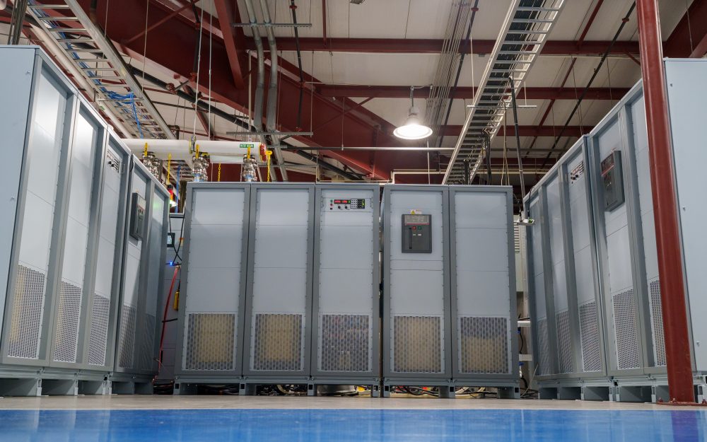
Prestazioni ad alta densità con raffreddamento a liquido
Uscita pulita e precisa da 500 kW a oltre 10 MW.
Gli alimentatori DC programmabili della Serie ML sfruttano piastre di raffreddamento a liquido avanzate e collettori interni per erogare 500 kW e 1.000 kW per cabinet con un'efficienza fino al 96%, raggiungendo una densità di potenza quasi quattro volte superiore rispetto ai modelli comparabili raffreddati ad aria, operando a piena potenza nominale fino a 50°C di temperatura ambiente. Basata sulla topologia current-fed di MagnaDC, la Serie ML offre una risoluzione di programmazione a 12 bit (0,025%), una regolazione linea/carico precisa e un'accuratezza di programmazione in tensione e corrente di ±0,075% con basso ripple, portando prestazioni di livello laboratorio a sistemi di test e di processo multi-megawatt.
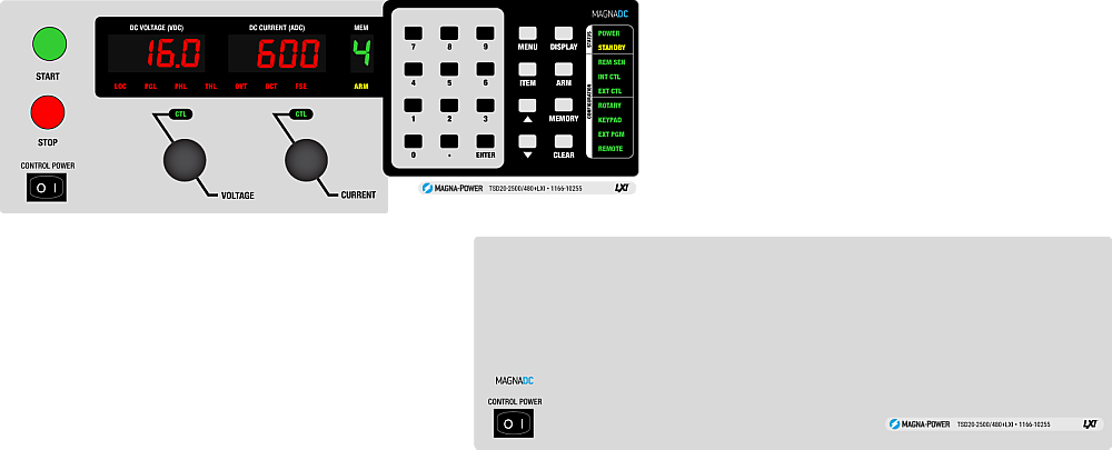
Controllo continuo dal pannello frontale con opzione pannello cieco
Operativo dove serve, nascosto dove non serve.
The standard SL front panel provides rotary and key-based control, bright digital metering, and clear status indicators, so operators can configure setpoints, start and stop the supply, and see system health at a glance. For OEMs and production tools, the optional blank (C-version) front panel removes local controls altogether while retaining full control via communication interfaces and rear 37-pin user I/O, keeping systems secure, clean, and operator-proof.
Configurato su ordinazione con opzioni integrate
Funzionalità standard complete, estendibili quando necessario.
Like the rest of the MagnaDC line, MT Series supplies start with a strong control base: SCPI over RS232, isolated rear User I/O, LabVIEW and IVI drivers, and Remote Interface Software included. From there, integrated options let you tailor each system for its role—High Isolation Output (+ISO) for extended series stacking, High Slew Rate Output (+HS) for faster dynamics, LXI TCP/IP Ethernet (+LXI) and IEEE-488 GPIB (+GPIB) for additional communications, plus protection and mechanical options such as an Integrated Blocking Diode (+BD) and Pedestal Base (+PB) for fixed installations.
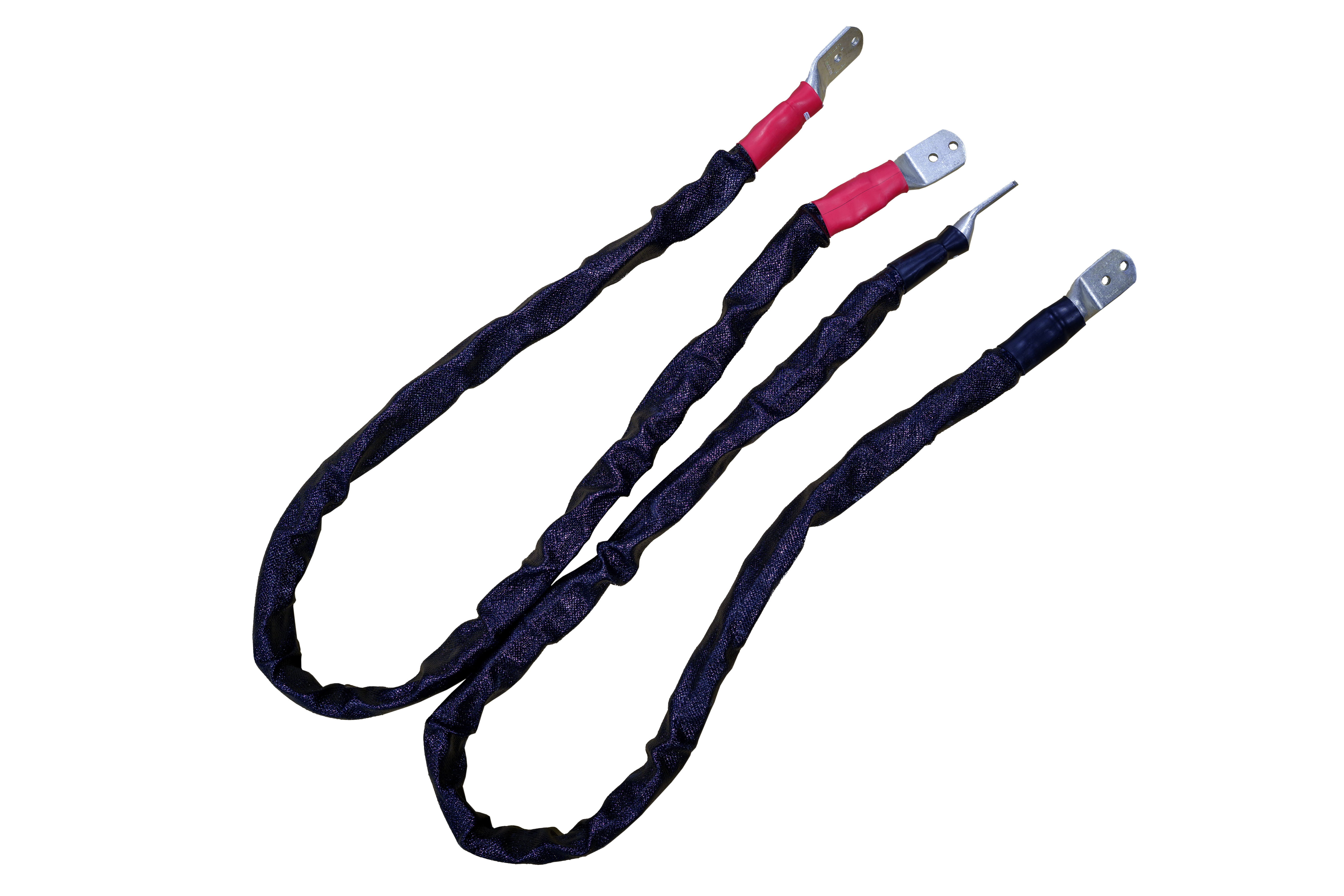
Neutralizzatori di armoniche per sistemi ad alta potenza più puliti
Riduci il THD alla sorgente per una conformità più semplice alla qualità dell'energia.
Le armoniche della corrente di ingresso sono un sottoprodotto intrinseco dei raddrizzatori trifase: un front-end standard a 6 impulsi produce correnti armoniche a 1, 5, 7, 11, 13… volte la fondamentale, con le sole componenti 5ª e 7ª rispettivamente al 20% e al 14% circa della fondamentale. Queste correnti possono eccitare carichi sensibili—come reattori per illuminazione con condensatori/induttori in serie—e rendere più difficile il rispetto delle linee guida sulla qualità dell'energia come IEEE 519. Il modo più affidabile per ridurre al minimo i problemi di armoniche è eliminare la corrente armonica alla sorgente.
Per i sistemi ad alta potenza, Magna-Power produce Neutralizzatori di Armoniche con avvolgimenti speciali che moltiplicano il numero delle fasi di ingresso e riducono drasticamente il THD della corrente di ingresso, in modo passivo. Gli alimentatori Magna-Power standard da 1,5–150 kW generano una forma d'onda a 6 impulsi, mentre i modelli MT Series da 250 kW e ML Series da 500 kW integrano un Neutralizzatore di Armoniche a 12 impulsi e i modelli ML Series da 1000 kW integrano un Neutralizzatore di Armoniche a 24 impulsi—in modo trasparente per l'utente.

Rugged by design: safety + reliability, as you'd expect from Magna-Power.

Elaborazione di potenza affidabile a corrente impressa
Robusto per design: topologia autoprotettiva per la massima operatività.
The SLx Series uses a high-frequency, current-fed architecture that adds a control stage beyond conventional voltage-fed designs. This topology inherently limits fault energy—avoiding fast-rising current spikes and magnetic core saturation so the supply self-protects and your load stays safe. Paired with state-of-the-art SiC power semiconductors, SLx delivers class-leading power density, efficiency, and reliability, including continuous full-power operation up to 50°C ambient.
- Current-fed architecture with an added control stage vs. voltage-fed.
- Inherent surge immunity—no current spikes or core saturation.
- Self-protecting behavior under fault conditions.
- SiC devices for high density and efficiency; full power to 50°C.
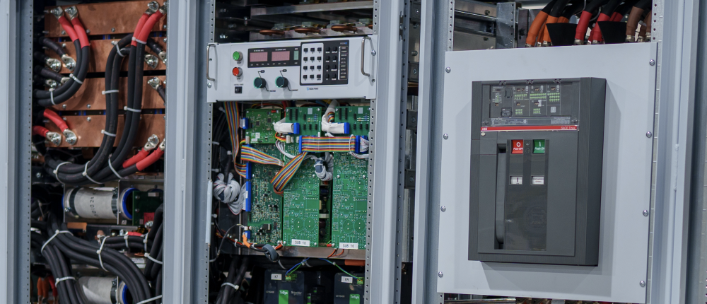
Caratteristiche di sicurezza e interlock
Avvio graduale, protezione programmabile e disconnessione meccanica della linea per una sicurezza reale.
MagnaDC supplies start gently and watch continuously. A soft-start stage keeps inrush below steady-state draw, while built-in diagnostics monitor line, thermal, and control conditions. In standby or on a diagnostic fault, an embedded AC contactor mechanically disconnects the mains, assuring the unit only processes power when intended. Faults are shown on the front-panel status display, through 5V digital outputs, and are queryable via SCPI.
-
Programmable trips: Over voltage (OVT) and over current (OCT)/
-
Control integrity: Program-line over-voltage detection.
-
Thermal protection: Over temperature on internal heatsinks.
-
Interlock/E-stop fault monitoring as a standard diagnostic.
-
Field integration: 5V interlock input (with 5V reference) for a dry-contact, latching inhibit with control power maintained.
From lab scripts to factory PLCs, flexible programming & integration.
Integrazione software semplificata
Comandi leggibili, risultati rapidi—funziona con qualsiasi linguaggio.
Gli alimentatori MagnaDC offrono un'API testuale chiara con SCPI nativo, un linguaggio di comando basato su ASCII inviato tramite comunicazioni socket. Oltre 40 comandi ben documentati coprono avvio/arresto, set point per tensione, corrente, misurazioni ad alta precisione e configurazione completa—così i vostri script e sistemi passano rapidamente dal proof-of-concept alla produzione.
- Set di comandi SCPI con comportamento coerente.
- Avvio/arresto e protezioni: abilitazione dell'uscita, impostazione dei limiti di intervento, interrogazione dello stato.
- Letture ad alta precisione: tensione, corrente, potenza e feedback di sensing.
- Documentazione ed esempi orientati allo sviluppatore.
import serial
magnaPower = serial.Serial(port='COM4', baudrate=19200)
magnaPower.write('*IDN?\n'.encode())
print magna_power.readline()
magnaPower.write('VOLT 0\n'.encode())
magnaPower.write('CURR 0\n'.encode())
magnaPower.write('OUTP:START\n'.encode())
magnaPower.write('VOLT 270\n'.encode())
currSetPoints = [50, 100, 150, 250]
for currSetPoint in currSetPoints:
    print 'Setting Current to %s A' % currSetPoint
    magnaPower.write('CURR {0}\n'.format(currSetPoint).encode())
    magnaPower.write('MEAS:VOLT?\n'.encode())
    print magnaPower.readline()
    time.sleep(20)
magnaPower.write('OUTP:STOP\n'.encode())
magnaPower.close()
magna_power = serial('COM4', 'BaudRate', 19200);
fopen(magnaPower);
fprintf(magnaPower,'*IDN?');
idn = fscanf(magnaPower);
fprintf(magnaPower,'VOLT 0');
fprintf(magnaPower,'CURR 0');
fprintf(magnaPower,'OUTP:START');
fprintf(magnaPower,'VOLT 270');
for currSetPoint in [50, 100, 150, 250]
    display('Setting Current to '+currSetPoint+' A');
    fprintf(magnaPower, 'CURR '+currSetPoint);
    fprintf(magnaPower,'MEAS:VOLT?');
    display(fscanf(magnaPower));
    pause(20);
end
#include <stdio.h>
#include <stdint.h>
#include <string.h>
#include <windows.h>

int main()
{
    printf("Opening connection.\n");

    uint8_t recvBuffer[sizeof(uint8_t) * 256];
    memset(recvBuffer, 0, 256);

    // Choose the serial port name.
    // COM ports higher than COM9 need the \\.\ prefix, which is written as
    // "\\\\.\\" in C because we need to escape the backslashes.
    const char* device = "\\\\.\\COM4";

    // Choose the baud rate (bits per second).
    uint32_t baud_rate = 19200;

    HANDLE port = open_serial_port(device, baud_rate);
    if (port == INVALID_HANDLE_VALUE) { return 1; }

    char* scpiCmd = (char*)"*IDN?\n";
    size_t cmdLen = strlen(scpiCmd);
    int result = write_port(port, (uint8_t*)scpiCmd, cmdLen);
    if (result < 0)
        return -1;

    result = read_port(port, recvBuffer, 256);
    printf("Sent: %s\nReceived: %s\n", scpiCmd, recvBuffer);

    scpiCmd = (char*)"VOLT 0\n";
    cmdLen = strlen(scpiCmd);
    result = write_port(port, (uint8_t*)scpiCmd, cmdLen);
    if (result < 0)
        return -1;

    scpiCmd = (char*)"CURR 0\n";
    cmdLen = strlen(scpiCmd);
    result = write_port(port, (uint8_t*)scpiCmd, cmdLen);
    if (result < 0)
        return -1;

    scpiCmd = (char*)"OUTP:START\n";
    cmdLen = strlen(scpiCmd);
    result = write_port(port, (uint8_t*)scpiCmd, cmdLen);
    if (result < 0)
        return -1;

    scpiCmd = (char*)"VOLT 270\n";
    cmdLen = strlen(scpiCmd);
    result = write_port(port, (uint8_t*)scpiCmd, cmdLen);
    if (result < 0)
        return -1;

    char setPoints[4][5] = {"50", "100", "150", "200"};
    char setPointBuffer[40];
    scpiCmd = (char*)"MEAS:VOLT?\n";

    for (int i = 0; i < 4; i++)
    {
        sprintf(setPointBuffer, "CURR %s\n", setPoints[i]);
        printf("Setting current to %s A\n", setPoints[i]);
        cmdLen = strlen(setPointBuffer);
        result = write_port(port, (uint8_t*)setPointBuffer, cmdLen);
        if (result < 0)
            return -1;
        memset(recvBuffer, 0, 256);
        result = read_port(port, recvBuffer, 256);
        printf("Received: %s\n", recvBuffer);
        Sleep(20000);  // 20000ms = 20s
    }

    scpiCmd = (char*)"OUTP:STOP\n";
    cmdLen = strlen(scpiCmd);
    result = write_port(port, (uint8_t*)scpiCmd, cmdLen);
    if (result < 0)
        return -1;

    CloseHandle(port);

    printf("Connection closed.\n");
    return 0;
}
using System;
using System.IO.Ports;
using System.Threading;

namespace SerialCommunicationInCSharp
{
  public class Program
  {
    static bool _continue;
    static SerialPort serialPort;

    public static void Main(string[] args)
    {
      Thread readThread = new Thread(Read);

      Console.WriteLine("Opening connection.");

      // Create a new SerialPort object with default settings.
      serialPort = new SerialPort("COM4", 19200, Parity.None, 8, StopBits.One);

      // Set the read/write timeouts
      serialPort.ReadTimeout = 500;
      serialPort.WriteTimeout = 500;

      serialPort.Open();
      _continue = true;
      readThread.Start();

      Console.WriteLine("Sending: *IDN?");
      serialPort.WriteLine("*IDN?");

      serialPort.WriteLine("VOLT 0");
      serialPort.WriteLine("CURR 0");
      serialPort.WriteLine("OUTP:START");
      serialPort.WriteLine("VOLT 270");

      string[] currSetPoints = { "50", "100", "150", "250" };
ß
      for(int i = 0; i < currSetPoints.Length; i++)
      {
        serialPort.WriteLine(String.Format("'CURR {0}", currSetPoints[i]));
        serialPort.WriteLine("MEAS:VOLT?");
        Thread.Sleep(20000);
      }

      serialPort.WriteLine("OUTP:STOP");

      Console.WriteLine("Closing connection.");
      _continue = false;
      serialPort.Close();
      }

    public static void Read()
    {
      while (_continue)
      {
        try
        {
          string message = serialPort.ReadLine();
          Console.WriteLine("Received: " + message);
        }
        catch (TimeoutException) { }
      }
    }
  }
}

User I/O esterno per controllo PLC o simulazione PHIL
Collegalo come un modulo I/O—non è necessario alcun isolamento aggiuntivo.
Via the included rear 37-pin User I/O connector, MagnaDC supplies can be fully driven and monitored by external signals or a PLC. Voltage, current, OVT, and OCT set points are programmed with 0–10 V analog inputs, while each diagnostic condition has its own +5V digital status pin. Built-in +2.5V, +5V, and +10V reference rails let you use dry contacts without adding external supplies. All I/O is isolated from the output and referenced to earth ground as standard.
-
0–10 V analog programming for V, I, OVT, and OCT.
-
Per-fault digital outputs: each diagnostic has its own +5V pin.
-
Isolated user I/O referenced to earth ground—no extra isolators.
-
With High Slew Rate Output (+HS), high-bandwidth response and fast rise times support HIL/PHIL simulation applications.
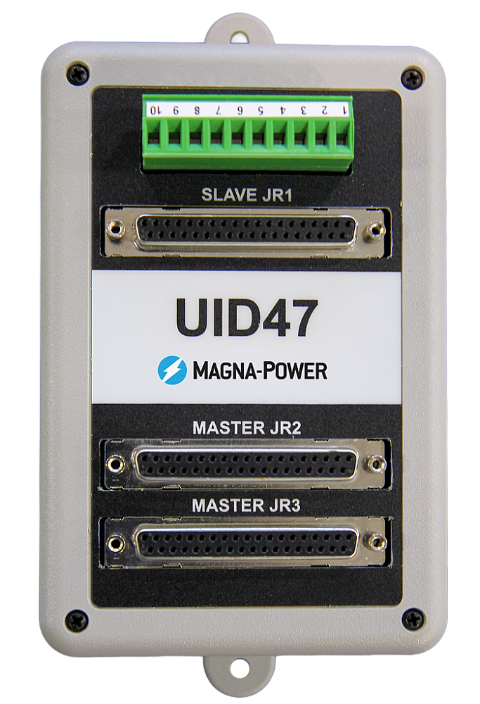
Funzionamento master-slave ad alte prestazioni
Scala tensione o corrente senza sacrificare le prestazioni.
All MagnaDC supplies support master-slave operation, using gate-drive signals from the master when configured for parallel, so the whole stack behaves like a single supply—with one control loop and no noisy long analog references. The optional UID47 accessory simplifies wiring for series or parallel sets with near-equal sharing.
-
Single control loop parallel operation: Master gate-drive to slaves for consistent dynamics.
-
Plug & play with the UID47, enabling parallel or series stacks with current/voltage sharing.
-
Series up to the DC isolation rating without added hardware.
No additional ORing diodes required for parallel operation.
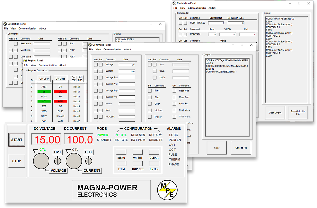
Software Magna-Power, driver LabVIEW e IVI
Dal pannello frontale virtuale all'automazione completa, pronti all'uso.
Ogni alimentatore MagnaDC include un driver IVI e un driver NI LabVIEW con un set completo di VI, oltre a programmi di esempio per comunicare con l'hardware in pochi minuti. Per il controllo diretto in stile pannello frontale da PC, il Remote Interface Software di Magna-Power offre una visione completa dell'alimentatore: dai comandi e registri alla calibrazione e al firmware.
-
Driver IVI e NI LabVIEW inclusi con set completo di VI.
-
Programmi di esempio per avviare rapidamente integrazione e test.
-
Remote Interface Software con:
-
Pannello frontale virtuale per il controllo manuale
-
Pannello comandi per esplorare e inviare comandi
-
Pannello registri per il monitoraggio dello stato in tempo reale
-
Pannello calibrazione per i potenziometri digitali interni
-
Pannello firmware per aggiornamenti in loco
-
Pannello modulazione per emulare profili non lineari
-
-
Tutte le interfacce di comunicazione supportate su software e driver per un'esperienza di programmazione coerente.
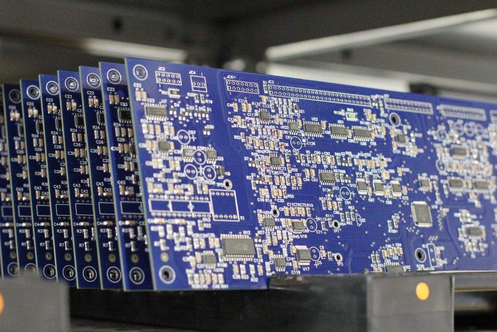
State-of-the-art USA manufacturing with worldwide support

Made in the USA
Produzione verticalmente integrata per un controllo qualità completo.
I prodotti Magna-Power sono progettati, costruiti, testati e assistiti presso la sede centrale di Magna-Power di 73.500 sq-ft a Flemington, New Jersey, dove lavorazioni metalliche, componenti magnetici, assemblaggio PCB e rodaggio vengono eseguiti internamente per un controllo rigoroso su qualità, costi e tempi di consegna.
- Prodotto negli USA: ingegneria, produzione e assistenza sotto un unico tetto.
- Produzione interna: lavorazioni metalliche, componenti magnetici, PCB SMT e finiture.
- Affidabilità comprovata: ogni unità completamente testata, calibrata e sottoposta a rodaggio.
Assistenza mondiale e supporto ricambi OEM
Competenza di fabbrica, risposta locale.
Magna-Power supporta i propri prodotti con centri di assistenza di fabbrica e autorizzati in Nord America, Europa, Regno Unito, Asia-Pacifico, Asia orientale e Sud America, utilizzando procedure di fabbrica e ricambi originali per ripristinare le unità alle specifiche originali, in garanzia e fuori garanzia.
- Copertura globale: sede centrale nel New Jersey e centri di assistenza autorizzati regionali.
- Riparazioni uniformi: diagnostica di fabbrica, istruzioni operative e schemi di sistema.
- Ricambi OEM originali: gruppi di ricambio testati per un servizio prevedibile e con tempi di fermo ridotti.
Model Ordering Guide
For both ordering and production, Serie ML models are uniquely defined by several key characteristics, as defined by the following diagram:

Serie ML Models
There are 38 different models in the Serie ML spanning power levels: 500 kW and 1000 kW. To determine the appropriate model:
- Select the desired Max Voltage (Vdc) from the left-most column.
- Select the desired Max Current (Adc) from the same row that contains your desired Max Voltage.
- Construct your model number according to the model ordering guide.
| Max Voltage Vdc |
500 kW | 1000 kW | Ripple mVrms |
Efficiency |
|---|---|---|---|---|
| Max Current Adc | ||||
| 100 | 5000 | — | 100 | 91% |
| 125 | 4000 | — | 100 | 91% |
| 160 | 3125 | — | 120 | 92% |
| 200 | 2500 | 5000 | 125 | 92% |
| 250 | 2000 | 4000 | 130 | 92% |
| 300 | 1666 | 3333 | 160 | 93% |
| 375 | 1333 | 2666 | 170 | 93% |
| 400 | 1250 | 2500 | 180 | 95% |
| 500 | 1000 | 2000 | 220 | 95% |
| 600 | 833 | 1666 | 300 | 95% |
| 800 | 625 | 1250 | 400 | 96% |
| 1000 | 500 | 1000 | 500 | 96% |
| 1250 | 400 | 800 | 500 | 96% |
| 1600 | 312 | 625 | 600 | 96% |
| 2000 | 250 | 500 | 800 | 96% |
| 2500 | 200 | 400 | 900 | 96% |
| 3000 | 166 | 333 | 1000 | 96% |
| 4000 | 125 | 250 | 1100 | 96% |
| 5000 | 100 | 200 | 1500 | 96% |
| 6000 | 83 | 166.6 | 2000 | 96% |
Specifications are subject to change without notice. Unless otherwise noted, all specifications measured at the product's maximum ratings.
AC Input Specifications
480 Vac, 3-phase
DC Output Specifications
Current control: ± 0.03% of rated current
Current control: ± 0.06% of rated current
Current control: 0.06%/ºC of rated current
< 200 ms, output current change from 0 to 63%
< 10 ms, output current change from 0 to 63%
Programming Specifications
Current: ± 0.075% of rated current
Current: ± 0.20% of rated current
Over Current: 10% to 110% of rated current
Analog programming impedance: 10 kΩ
Analog measurement outputs: 0-10V, 5 mA capacity
Analog measurement impedance: 100 Ω
Analog reference signal: 10 V, 5 mA capacity, 1 Ω
Digital control inputs impedance: 10 kΩ
Digital monitoring outputs: 5 V, 5 mA capacity
Digital reference signal: 5 V, 25 mA capacity
Interace Specifications
Referenced to ground; isolated from the DC output
See User Manual for pin layout
Physical Specifications
76.4” H x 48” W x 31.5” D (194.1 x 121.9 x 80.0 cm)
2500 lbs (1134 kg) 500 kW Harmonic Neutralizer
76.4” H x 24” W x 31.5” D (194.1 x 61.0 x 80.0 cm)
1500 lbs (680 kg)
76.4” H x 72” W x 31.5” D (194.1 x 182.9 x 80.0 cm)
3750 lbs (1701 kg) 1000 kW Harmonic Neutralizer
76.4” H x 48” W x 31.5” D (194.1 x 121.9 x 80.0 cm)
2850 lbs (1293 kg)
Environmental Specifications
Maximum inlet pressure: 80 psi
Inlet and outlet fittings provided: 1” Female NPT
Materials in coolant path: Copper pipe, PEX tubing, brass solenoid & fittings
Regulatory Specifications
CISPR 22 / EN 55022 Class A
The following are vectorized diagrams for the Serie ML. Refer to the Downloads section for downloadable drawings.


Integrated Options
Standard integrated options are available for Magna-Power products, allowing the product's performance and communication interfaces to be tailors to the specific application.
- Option
- +ISO
- Option
- +HS
- Option
- +GPIB

Accessories
External accessories and integration services available for this product.