ALx Serie
DC Electronic Load
- Size
- 3U to 24U
- Power
- 1.25 kW to 20 kW
- Manufactured
- USA
- Build-time
- 6-8 weeks
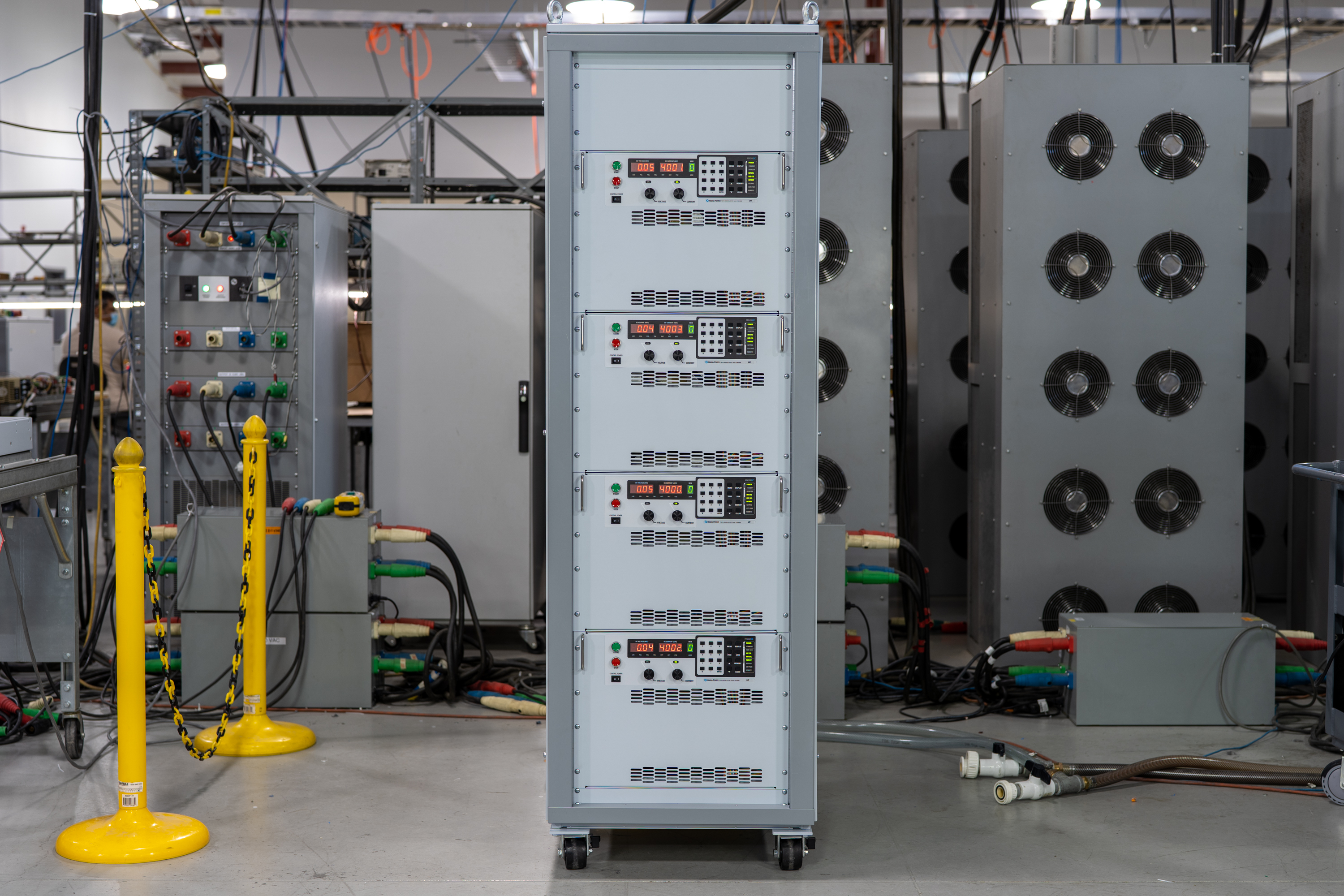
The ALx Series MagnaLOAD utilizes conventional linear MOSFET-based dissipative elements, allowing the series to achieve a very wide voltage-current operating range within the model’s maximum power rating. Using the same heat management innovations developed for Magna-Power’s high density programmable DC power supplies, the ALx Series’ conservative cooling ensures long product life with continuous full power operation in environments up to 50°C ambient operating temperature.

Talk with an expert
Do more with MagnaLINK™ distributed digital control.

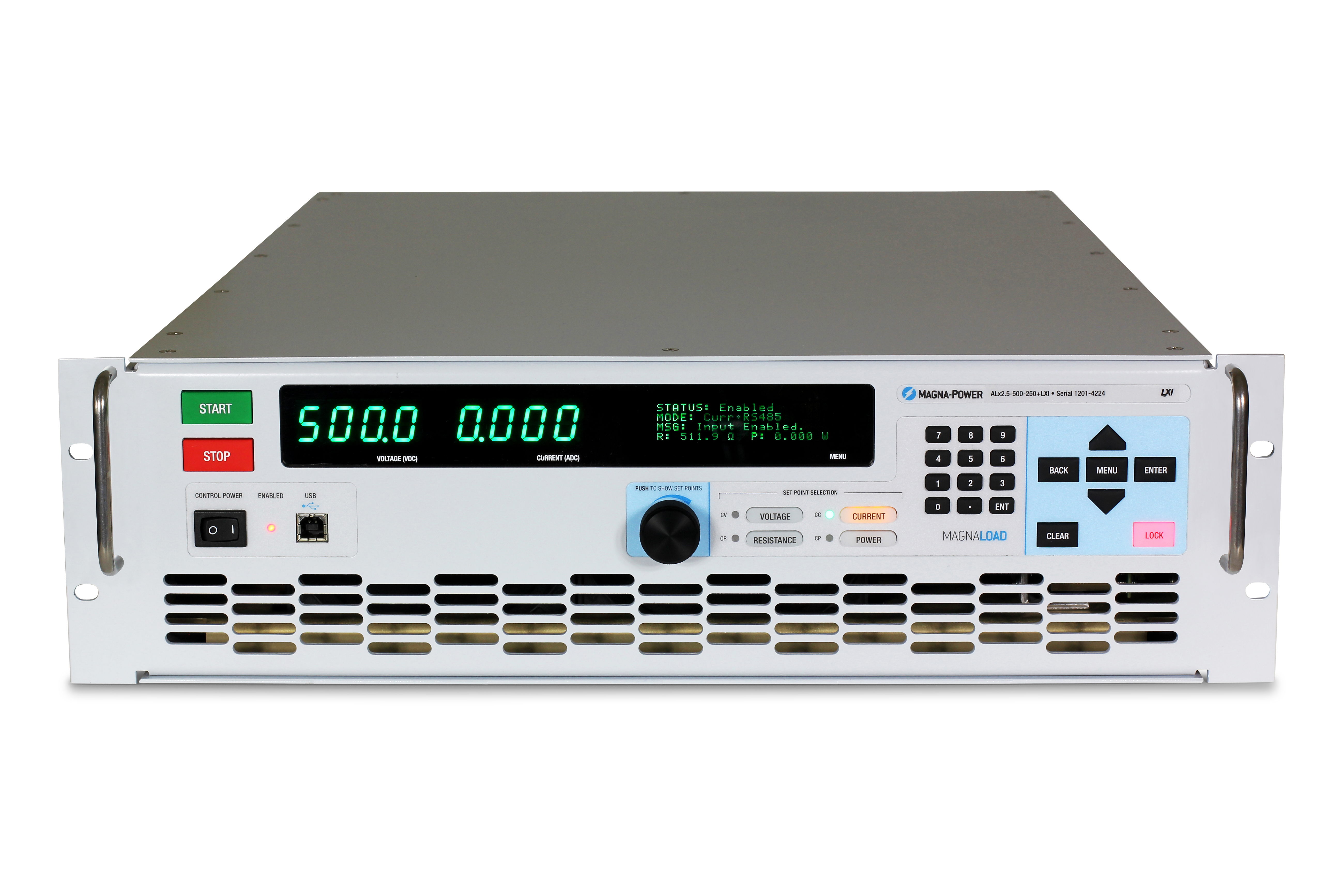
Präzise Steuerung & Messung
DSP-gesteuerte Präzision vom Sollwert bis zum Lastpunkt.
Die SLx Serie verfügt über Magna-Powers xGen MagnaLINK™ digitale Steuerungsplattform, die ein verteiltes Netzwerk von DSPs und Hochgeschwindigkeits-Board-to-Board-Kommunikation unter Verwendung eines intern entwickelten Low-Level-Kommunikationsprotokolls nutzt. Interne Gain-Scheduling-Verfahren mit feldabstimmbaren Verstärkungsfaktoren unterstützen ein breites Spektrum an Lastbedingungen.
- Spannungs-, Strom- und Leistungsregelung mit 16-Bit-Auflösung.
- Programmierbare Anstiegsratensteuerung.
- Native Stabilität von 100 ppm.
- Lokale, entfernte und kabellose Spannungsmessung für präzise Regelung am Lastpunkt.

Plug-and-Play Master-Slaving
Skalieren Sie die Leistung nahtlos mit aggregierten Systemwerten.
Zwei MagnaLINK-Anschlüsse bieten eine digitale Hybrid-Master-Slave-Verbindung der nächsten Generation, sodass ein Gerät einen synchronisierten Stapel steuern kann. Erweitern Sie die Stromkapazität durch Parallelschaltung von bis zu 16 Geräten. Ein sekundärer Stromsensor liefert dem Master analoge Stromwerte in Echtzeit für eine präzise Aggregation und Anzeige.
- Parallelschaltung von bis zu 16 Geräten mit einfacher Schnittstellenverdrahtung.
- Ein Sollwert; synchronisierter Ausgang und Schutzfunktionen.
- Sekundäre Stromsensor-Rückmeldung für präzise Lastverteilung.
- Automatische Konfiguration und aggregierte Messwerte auf einem einzigen Master-Display.
From lab scripts to factory PLCs, flexible programming & integration.
Softwareintegration leicht gemacht
Lesbare Befehle, schnelle Ergebnisse – funktioniert mit jeder Programmiersprache.
Die SLx Serie bietet eine klare, textbasierte API mit nativer SCPI- und Modbus-Unterstützung. Über 60 gut dokumentierte Befehle decken Start/Stopp, Sollwerte für Spannung, Strom und Leistung, Anstiegsratensteuerung, hochpräzise Messungen und vollständige Konfiguration ab – so gelangen Ihre Skripte und Systeme schnell vom Proof-of-Concept in die Produktion.
- SCPI- und Modbus-Befehlssätze mit einheitlichem Verhalten.
- Start/Stopp und Schutzfunktionen: Ausgang aktivieren, Grenzwerte setzen, Status abfragen.
- Hochpräzise Messwerte: Spannung, Strom, Leistung und Sense-Rückmeldung.
- Entwicklerorientierte Dokumentation und Beispiele.
import serial
magnaPower = serial.Serial(port='COM4', baudrate=115200)
magnaPower.write('*IDN?\n'.encode())
print magna_power.readline()
magnaPower.write('VOLT 0\n'.encode())
magnaPower.write('CURR 0\n'.encode())
magnaPower.write('OUTP:START\n'.encode())
magnaPower.write('VOLT 270\n'.encode())
currSetPoints = [50, 100, 150, 250]
for currSetPoint in currSetPoints:
    print 'Setting Current to %s A' % currSetPoint
    magnaPower.write('CURR {0}\n'.format(currSetPoint).encode())
    magnaPower.write('MEAS:VOLT?\n'.encode())
    print magnaPower.readline()
    time.sleep(20)
magnaPower.write('OUTP:STOP\n'.encode())
magnaPower.close()
magna_power = serial('COM4', 'BaudRate', 115200);
fopen(magnaPower);
fprintf(magnaPower,'*IDN?');
idn = fscanf(magnaPower);
fprintf(magnaPower,'VOLT 0');
fprintf(magnaPower,'CURR 0');
fprintf(magnaPower,'OUTP:START');
fprintf(magnaPower,'VOLT 270');
for currSetPoint in [50, 100, 150, 250]
    display('Setting Current to '+currSetPoint+' A');
    fprintf(magnaPower, 'CURR '+currSetPoint);
    fprintf(magnaPower,'MEAS:VOLT?');
    display(fscanf(magnaPower));
    pause(20);
end
#include <stdio.h>
#include <stdint.h>
#include <string.h>
#include <windows.h>

int main()
{
    printf("Opening connection.\n");

    uint8_t recvBuffer[sizeof(uint8_t) * 256];
    memset(recvBuffer, 0, 256);

    // Choose the serial port name.
    // COM ports higher than COM9 need the \\.\ prefix, which is written as
    // "\\\\.\\" in C because we need to escape the backslashes.
    const char* device = "\\\\.\\COM4";

    // Choose the baud rate (bits per second).
    uint32_t baud_rate = 115200;

    HANDLE port = open_serial_port(device, baud_rate);
    if (port == INVALID_HANDLE_VALUE) { return 1; }

    char* scpiCmd = (char*)"*IDN?\n";
    size_t cmdLen = strlen(scpiCmd);
    int result = write_port(port, (uint8_t*)scpiCmd, cmdLen);
    if (result < 0)
        return -1;

    result = read_port(port, recvBuffer, 256);
    printf("Sent: %s\nReceived: %s\n", scpiCmd, recvBuffer);

    scpiCmd = (char*)"VOLT 0\n";
    cmdLen = strlen(scpiCmd);
    result = write_port(port, (uint8_t*)scpiCmd, cmdLen);
    if (result < 0)
        return -1;

    scpiCmd = (char*)"CURR 0\n";
    cmdLen = strlen(scpiCmd);
    result = write_port(port, (uint8_t*)scpiCmd, cmdLen);
    if (result < 0)
        return -1;

    scpiCmd = (char*)"OUTP:START\n";
    cmdLen = strlen(scpiCmd);
    result = write_port(port, (uint8_t*)scpiCmd, cmdLen);
    if (result < 0)
        return -1;

    scpiCmd = (char*)"VOLT 270\n";
    cmdLen = strlen(scpiCmd);
    result = write_port(port, (uint8_t*)scpiCmd, cmdLen);
    if (result < 0)
        return -1;

    char setPoints[4][5] = {"50", "100", "150", "200"};
    char setPointBuffer[40];
    scpiCmd = (char*)"MEAS:VOLT?\n";

    for (int i = 0; i < 4; i++)
    {
        sprintf(setPointBuffer, "CURR %s\n", setPoints[i]);
        printf("Setting current to %s A\n", setPoints[i]);
        cmdLen = strlen(setPointBuffer);
        result = write_port(port, (uint8_t*)setPointBuffer, cmdLen);
        if (result < 0)
            return -1;
        memset(recvBuffer, 0, 256);
        result = read_port(port, recvBuffer, 256);
        printf("Received: %s\n", recvBuffer);
        Sleep(20000);  // 20000ms = 20s
    }

    scpiCmd = (char*)"OUTP:STOP\n";
    cmdLen = strlen(scpiCmd);
    result = write_port(port, (uint8_t*)scpiCmd, cmdLen);
    if (result < 0)
        return -1;

    CloseHandle(port);

    printf("Connection closed.\n");
    return 0;
}
using System;
using System.IO.Ports;
using System.Threading;

namespace SerialCommunicationInCSharp
{
  public class Program
  {
    static bool _continue;
    static SerialPort serialPort;

    public static void Main(string[] args)
    {
      Thread readThread = new Thread(Read);

      Console.WriteLine("Opening connection.");

      // Create a new SerialPort object with default settings.
      serialPort = new SerialPort("COM4", 115200, Parity.None, 8, StopBits.One);

      // Set the read/write timeouts
      serialPort.ReadTimeout = 500;
      serialPort.WriteTimeout = 500;

      serialPort.Open();
      _continue = true;
      readThread.Start();

      Console.WriteLine("Sending: *IDN?");
      serialPort.WriteLine("*IDN?");

      serialPort.WriteLine("VOLT 0");
      serialPort.WriteLine("CURR 0");
      serialPort.WriteLine("OUTP:START");
      serialPort.WriteLine("VOLT 270");

      string[] currSetPoints = { "50", "100", "150", "250" };
ß
      for(int i = 0; i < currSetPoints.Length; i++)
      {
        serialPort.WriteLine(String.Format("'CURR {0}", currSetPoints[i]));
        serialPort.WriteLine("MEAS:VOLT?");
        Thread.Sleep(20000);
      }

      serialPort.WriteLine("OUTP:STOP");

      Console.WriteLine("Closing connection.");
      _continue = false;
      serialPort.Close();
      }

    public static void Read()
    {
      while (_continue)
      {
        try
        {
          string message = serialPort.ReadLine();
          Console.WriteLine("Received: " + message);
        }
        catch (TimeoutException) { }
      }
    }
  }
}

Externer User I/O
Flexible, isolierte analog-digitale Steuerungen.
Alle Netzgeräte der SLx Serie werden standardmäßig mit einem 26-poligen D-Sub-Stecker geliefert, der als externer User I/O bezeichnet wird. Dieser Stecker bietet:
- 8 digitale Ausgänge (5V-Logik)
- 4 digitale Eingänge (5V-Logik)
- 4 analoge Ausgänge (0-10V-Logik)
- 4 analoge Eingänge (0-10V-Logik)
Der externe User I/O ist von den Ausgangsklemmen isoliert und auf Erdung bezogen. Die Pins des Steckers sind benutzerkonfigurierbar, sodass Anwender die für ihre Anwendung benötigten Funktionen auswählen können und gleichzeitig zukünftige Erweiterungen für neue Funktionen möglich sind. Nutzen Sie die digitalen Ausgänge, um das Netzgerät beispielsweise mit externen Freigabesignalen oder digitaler Fehlerüberwachungslogik zu integrieren, oder überwachen Sie Spannung und Strom über die analogen 0-10V-Ausgänge. Ein dedizierter analoger Hochgeschwindigkeitseingang wird ebenfalls bereitgestellt, der mit 2 kHz abgetastet wird und eine nahezu Echtzeit-Steuerung ermöglicht.
Industrielle Kommunikation & Steuerung
Vom Labornetzwerk bis zur SPS—Integration nach Ihren Vorgaben.
Die Serie wird anschlussfertig mit dualem USB (Front & Rückseite) und RS485 geliefert und unterstützt SCPI und Modbus. Für Netzwerke und Fabrikautomation stehen vollständig integrierte Optionen mit Modbus-Unterstützung, umfassender Dokumentation und Gerätebeschreibungsdateien zur Verfügung, die die SPS-Einrichtung und das Tag-Mapping beschleunigen.
- Serienmäßig dualer USB (Front + Rückseite) und RS485.
- TCP/IP-Netzwerkanbindung mit der Option LXI TCP/IP Ethernet (+LXI)
- SPS-Feldbusoptionen: CANopen (+CAN), EtherCAT (+ECAT), EtherNet/IP (+EIP), Modbus-TCP (+MTCP), PROFINET (+PROF).
- Gerätedateien enthalten: EDS (CANopen/EtherNet/IP), ESI XML (EtherCAT), GSDML (PROFINET) für schnelle SPS-Integration.
- Vollständige Befehlsdokumentation, Beispiele und Diagnosefunktionen.
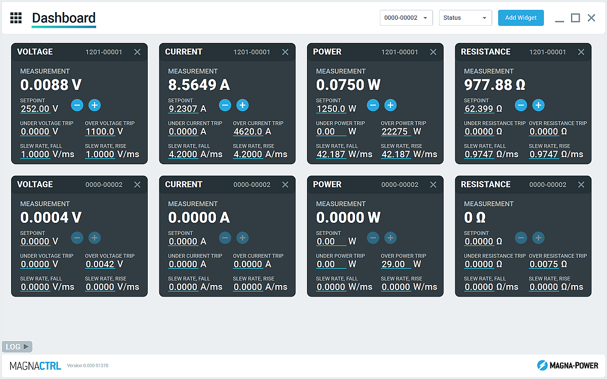
Enthaltene MagnaCTRL Software
Multi-Produkt-Dashboard-Steuerung, Diagnose und Updates – sofort einsatzbereit.
MagnaCTRL ist eine moderne Multi-Produkt-Steuerungsplattform, die bei xGen Produkten enthalten ist. Erstellen Sie Dashboards, konfigurieren Sie I/O, führen Sie Updates durch und greifen Sie auf umfassende Diagnosen zu – alles aus einer Anwendung.
- Konfigurierbares Dashboard: Widgets hinzufügen/anordnen, um mehrere verbundene Geräte zu überwachen und zu steuern.
- Product Explorer: Geräte automatisch erkennen, Verbindungen speichern und in zukünftigen Sitzungen automatisch wieder verbinden.
- Externes User-I/O-Panel: 26-Pin-I/O zuordnen, Pin-Maps für schnelle Inbetriebnahmen exportieren/importieren.
- Firmware-/Software-Updates: Neue Versionen automatisch erkennen; bei Bedarf manuelle Updates offline durchführen (siehe Changelog)
- Kalibrierungswerkzeuge: Programmier-/Messverstärkungen und -Offsets anpassen; mit Anleitung Regelkreisverstärkungen abstimmen.
- Datenprotokollierung: Grafische Ausgabe und .csv-Protokollierung von Spannungs-, Strom- und Leistungsmessungen sowie Einstellungen über die Zeit
State-of-the-art USA manufacturing with worldwide support

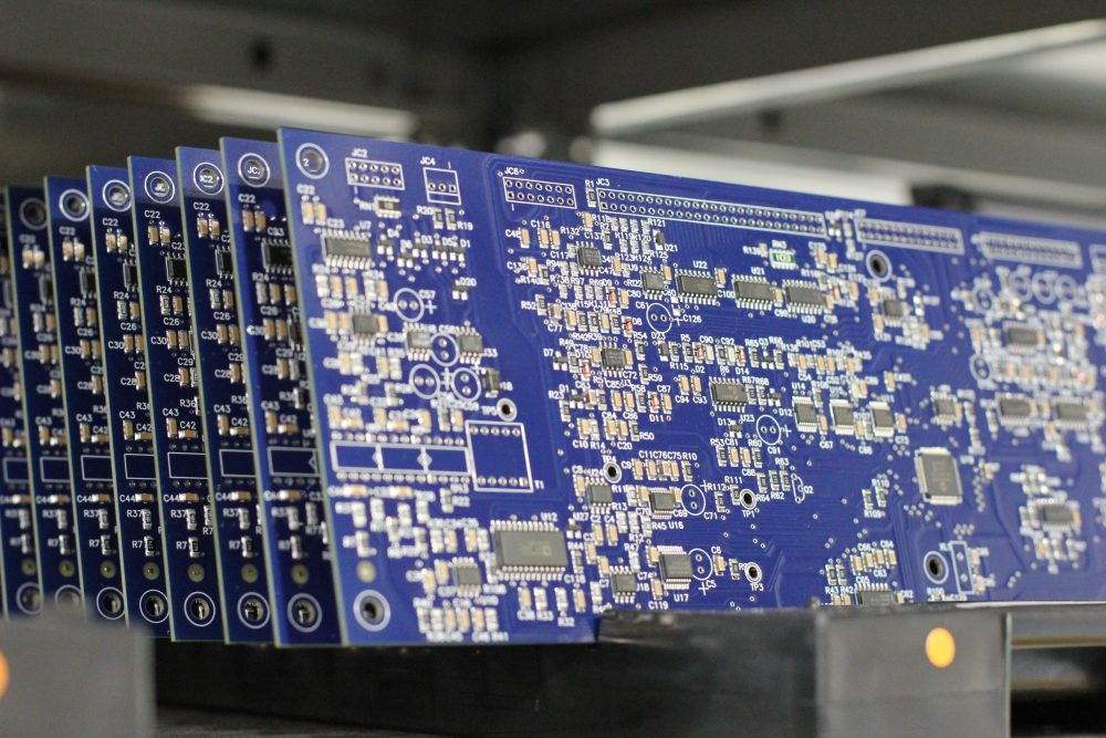
Made in the USA
Vertikal integrierte Fertigung für vollständige Qualitätskontrolle.
Magna-Power Produkte werden am 73.500 sq-ft großen Hauptsitz von Magna-Power in Flemington, New Jersey, entworfen, gebaut, getestet und gewartet. Metallbearbeitung, Magnetfertigung, PCB-Bestückung und Burn-in erfolgen vollständig im eigenen Haus – für maximale Kontrolle über Qualität, Kosten und Lieferzeiten.
- Made in USA: Entwicklung, Fertigung und Service unter einem Dach.
- Eigenfertigung: Metallbearbeitung, Magnetfertigung, SMT-PCBs und Oberflächenbehandlung.
- Bewährte Zuverlässigkeit: Jedes Gerät wird vollständig getestet, kalibriert und eingebrannt.
Weltweiter Service & OEM-Ersatzteilsupport
Fachwissen ab Werk, Reaktion vor Ort.
Magna-Power unterstützt seine Produkte mit werks- und autorisierten Servicezentren in Nordamerika, Europa, Großbritannien, dem asiatisch-pazifischen Raum, Ostasien und Südamerika – mit werkseitigen Verfahren und Originalteilen, um Geräte innerhalb und außerhalb der Garantie auf die ursprünglichen Spezifikationen zurückzusetzen.
- Globale Abdeckung: Hauptsitz in New Jersey sowie regionale autorisierte Servicezentren.
- Einheitliche Reparaturen: Werksdiagnosen, Arbeitsanweisungen und Systemdiagramme.
- Original-OEM-Teile: Geprüfte Ersatzbaugruppen für planbaren Service mit minimalen Ausfallzeiten.
Model Ordering Guide
For both ordering and production, ALx Series models are uniquely defined by several key characteristics, as defined by the following diagram:

ALx Series Models
There are 27 different models in the ALx Series spanning power levels: 1.25 kW, 2.5 kW, 5 kW, 7.5 kW, 10 kW, 12.5 kW, 15 kW, 17.5 kW, 20 kW. To determine the appropriate model:
- Select the desired Max Voltage (Vdc) from the left-most column.
- Select the desired Max Current (Adc) from the same row that contains your desired Max Voltage.
- Construct your model number according to the model ordering guide.
| Model | Max Power kW |
Max Voltage Vdc |
Max Current Adc |
Package Type | Min Voltage Vdc |
Max Resistance Ω |
|---|---|---|---|---|---|---|
| ALx1.25-200-300 | 1.25 | 200 | 300 | Rack-mount | 2.5 | 70.40 |
| ALx1.25-500-125 | 1.25 | 500 | 125 | Rack-mount | 6.0 | 448.00 |
| ALx1.25-1000-37.5 | 1.25 | 1000 | 37.5 | Rack-mount | 7.5 | 1792.00 |
| ALx2.5-200-600 | 2.5 | 200 | 600 | Rack-mount | 2.5 | 70.40 |
| ALx2.5-500-250 | 2.5 | 500 | 250 | Rack-mount | 6.0 | 448.00 |
| ALx2.5-1000-75 | 2.5 | 1000 | 75 | Rack-mount | 7.5 | 1792.00 |
| ALx5-200-1200 | 5 | 200 | 1200 | Floor-standing | 2.5 | 35.20 |
| ALx5-500-500 | 5 | 500 | 500 | Floor-standing | 6.0 | 224.00 |
| ALx5-1000-150 | 5 | 1000 | 150 | Floor-standing | 7.5 | 896.00 |
| ALx7.5-200-1800 | 7.5 | 200 | 1800 | Floor-standing | 2.5 | 23.47 |
| ALx7.5-500-750 | 7.5 | 500 | 750 | Floor-standing | 6.0 | 149.33 |
| ALx7.5-1000-225 | 7.5 | 1000 | 225 | Floor-standing | 7.5 | 597.33 |
| ALx10-200-2400 | 10 | 200 | 2400 | Floor-standing | 2.5 | 17.60 |
| ALx10-500-1000 | 10 | 500 | 1000 | Floor-standing | 6.0 | 112.00 |
| ALx10-1000-300 | 10 | 1000 | 300 | Floor-standing | 7.5 | 448.00 |
| ALx12.5-200-3000 | 12.5 | 200 | 3000 | Floor-standing | 2.5 | 14.08 |
| ALx12.5-500-1250 | 12.5 | 500 | 1250 | Floor-standing | 6.0 | 89.60 |
| ALx12.5-1000-375 | 12.5 | 1000 | 375 | Floor-standing | 7.5 | 358.40 |
| ALx15-200-3600 | 15 | 200 | 3600 | Floor-standing | 2.5 | 11.73 |
| ALx15-500-1500 | 15 | 500 | 1500 | Floor-standing | 6.0 | 74.67 |
| ALx15-1000-450 | 15 | 1000 | 450 | Floor-standing | 7.5 | 298.67 |
| ALx17.5-200-4200 | 17.5 | 200 | 4200 | Floor-standing | 2.5 | 10.06 |
| ALx17.5-500-1750 | 17.5 | 500 | 1750 | Floor-standing | 6.0 | 64.00 |
| ALx17.5-1000-525 | 17.5 | 1000 | 525 | Floor-standing | 7.5 | 256.00 |
| ALx20-200-4800 | 20 | 200 | 4800 | Floor-standing | 2.5 | 8.80 |
| ALx20-500-2000 | 20 | 500 | 2000 | Floor-standing | 6.0 | 56.00 |
| ALx20-1000-600 | 20 | 1000 | 600 | Floor-standing | 7.5 | 224.00 |
Specifications are subject to change without notice. Unless otherwise noted, all specifications measured at the product's maximum ratings.
AC Input Specifications
200-240 Vac (UI2: Universal Input 2); Available on 20 kW Models
Programming Interface Specifications
USB Host (Rear): Type B
RS485 (Rear): RJ-45
MagnaLINK™: RJ-25 x 2
GPIB (Rear): IEEE-488
Referenced to Earth ground; isolated from the DC input
See User Manual for pin layout
Programming Specifications
Current: ±0.2% of full scale current rating
Power: ±0.3% of full scale power rating
Resistance: ±0.3% of full scale resistance rating
Current Mode: 2 ms, 10% to 90% full scale current rating
Power Mode: 100 ms, 10% to 90% full scale power rating
Resistance Mode: 200 ms, 10% to 90% full scale resistance rating
Under Voltage: 0% to 110% of full scale voltage rating
Over Current: 10% to 110% of full scale current rating
Over Power: 10% to 110% of full scale power rating
External User I/O Specifications
Digital Input Impedance: 10 kΩ
Digital Monitoring Voltage: 5V, 32 mA capacity
Digital Reference Voltage: 5V, 20 mA capacity
Analog Programming Voltage: 0-10 V
Analog Programming Resolution: 12-bit, 0.025%
Analog Monitoring Voltage: 0-10 V, 3 mA capacity
Analog Monitoring Impedance: 0.005 Ω
Analog Monitoring Accuracy: 0.05% of full scale
Analog Reference Voltage: 10 V, 20 mA capacity
Physical Specifications
5.25” H x 19” W x 24” D (13.34 x 48.26 x 60.96 cm)
40 lbs (18.1 kg)
5.25” H x 19” W x 24” D (13.34 x 48.26 x 60.96 cm)
65 lbs (29.5 kg)
30.7” H x 24” W x 31.5” D (78.0 x 61.0 x 80.0 cm)
255 lbs (115.7 kg)
30.7” H x 24” W x 31.5” D (78.0 x 61.0 x 80.0 cm)
320 lbs (145.2 kg)
30.7” H x 24” W x 31.5” D (78.0 x 61.0 x 80.0 cm)
385 lbs (174.6 kg)
58.25” H x 24” W x 31.5” D (148.0 x 61.0 x 80.0 cm)
500 lbs (226.8 kg)
58.25” H x 24” W x 31.5” D (148.0 x 61.0 x 80.0 cm)
565 lbs (256.3 kg)
58.25” H x 24” W x 31.5” D (148.0 x 61.0 x 80.0 cm)
630 lbs (285.8 kg)
58.25” H x 24” W x 31.5” D (148.0 x 61.0 x 80.0 cm)
695 lbs (315.3 kg)
Environmental Specifications
Regulatory Specifications
CISPR 22 / EN 55022 Class A
CSA C22.2 No. 61010-1:12; A1:2018
UL 61010-1:Ed.3,2012(R2019)
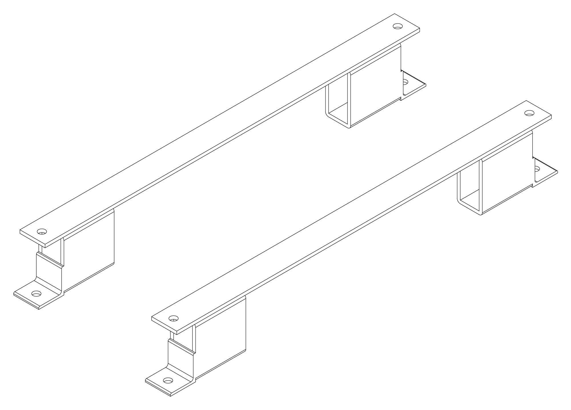
The following are vectorized diagrams for the ALx Series. Refer to the Downloads section for downloadable drawings.


Integrated Options
Standard integrated options are available for Magna-Power products, allowing the product's performance and communication interfaces to be tailors to the specific application.
- Option
- +CAN
- Option
- +ECAT
- Option
- +EIP
- Option
- +LXI

- Option
- +MTCP
Accessories
External accessories and integration services available for this product.