ALx 시리즈
DC Electronic Load
- Size
- 3U to 24U
- Power
- 1.25 kW to 20 kW
- Manufactured
- USA
- Build-time
- 6-8 weeks
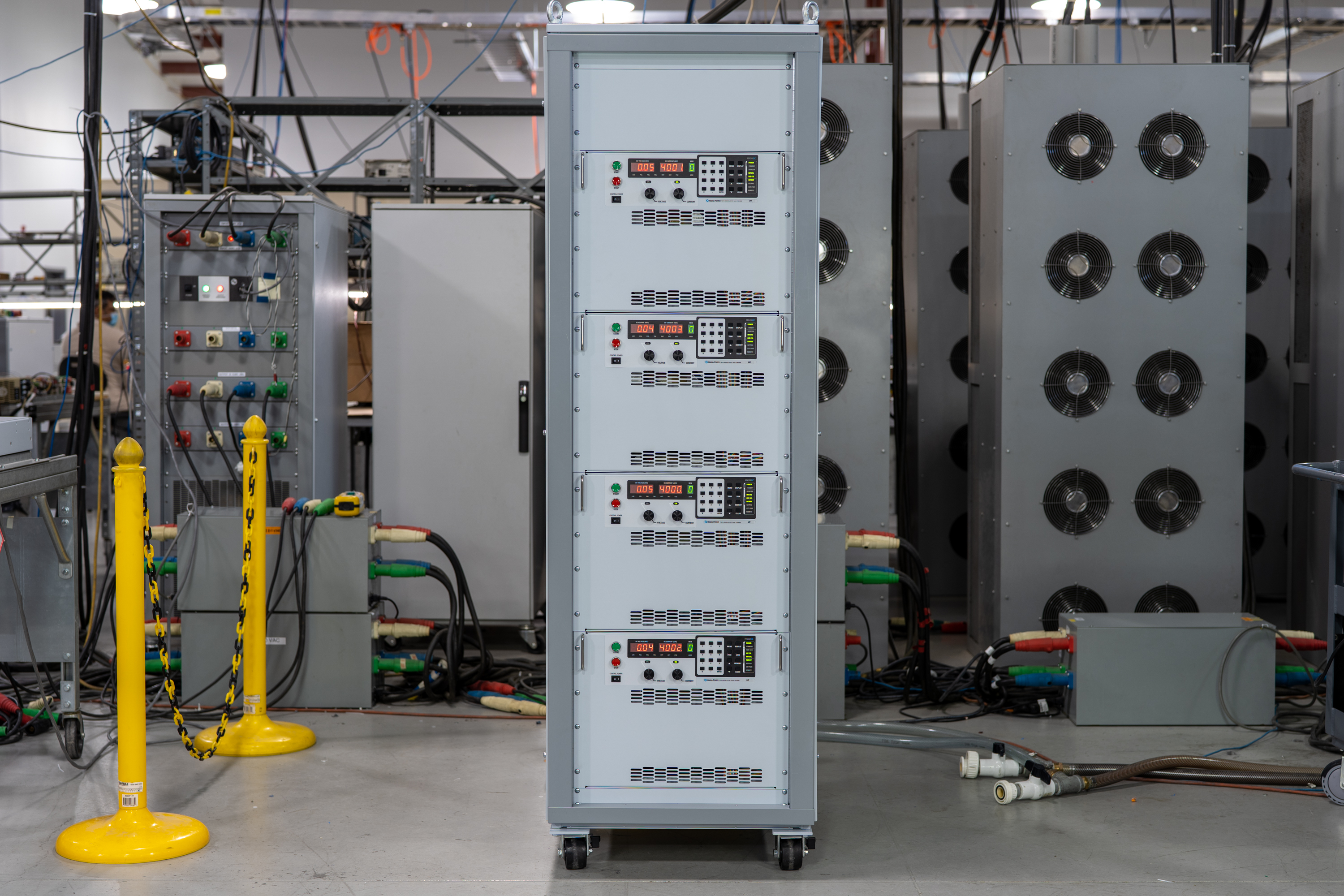
The ALx Series MagnaLOAD utilizes conventional linear MOSFET-based dissipative elements, allowing the series to achieve a very wide voltage-current operating range within the model’s maximum power rating. Using the same heat management innovations developed for Magna-Power’s high density programmable DC power supplies, the ALx Series’ conservative cooling ensures long product life with continuous full power operation in environments up to 50°C ambient operating temperature.

Talk with an expert
Do more with MagnaLINK™ distributed digital control.

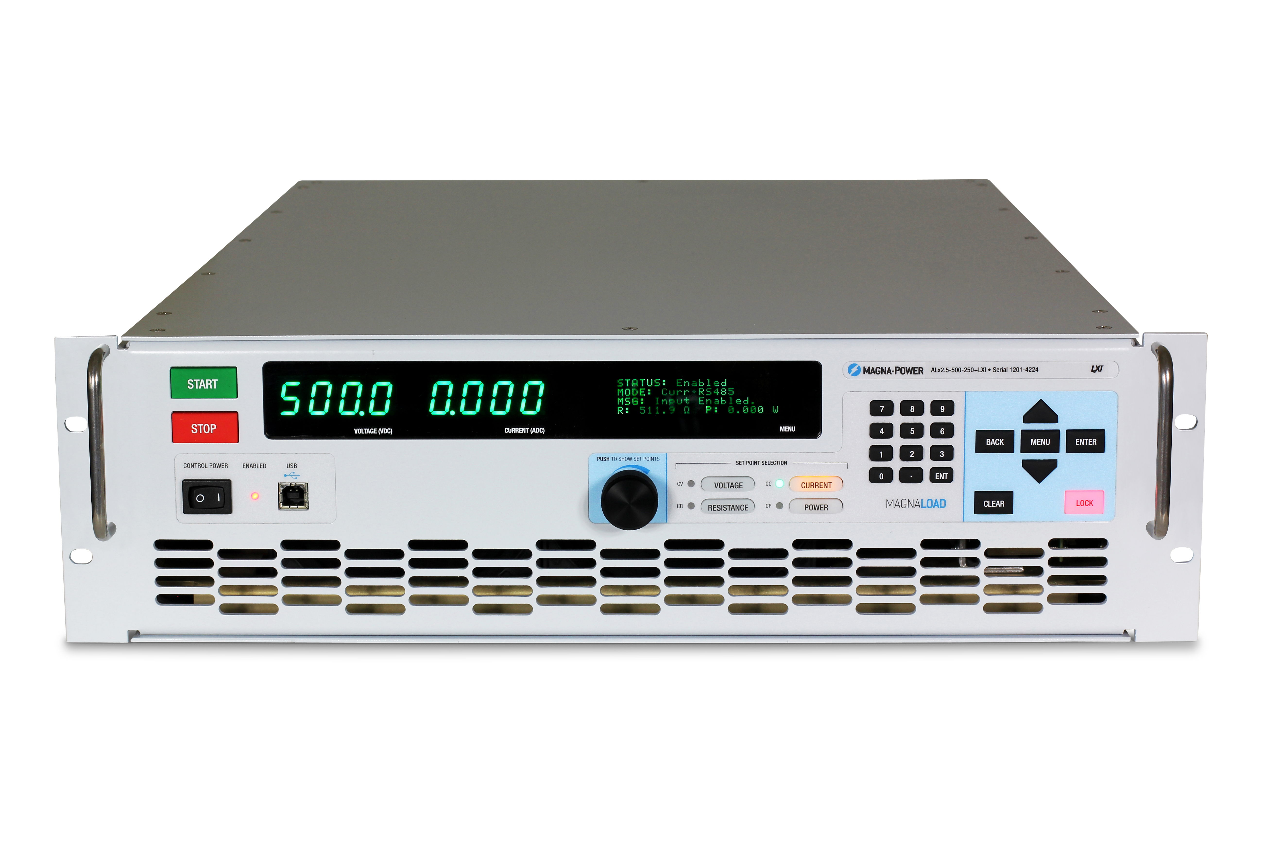
정밀 제어 및 측정
설정값에서 부하 지점까지 DSP 기반의 정밀 제어.
SLx 시리즈는 Magna-Power의 xGen MagnaLINK™ 디지털 제어 플랫폼을 탑재하고 있으며, 자체 개발한 저수준 통신 프로토콜을 활용하는 분산 DSP 네트워크와 고속 보드 간 통신을 사용합니다. 내부 게인 스케줄링과 현장 조정 가능한 게인으로 광범위한 부하 조건을 지원합니다.
- 16비트 분해능의 전압, 전류 및 전력 제어.
- 프로그래밍 가능한 슬루 레이트 제어.
- 기본 100 ppm 안정성.
- 정확한 부하 지점 레귤레이션을 위한 로컬, 원격 및 무선 전압 감지.

플러그 앤 플레이 마스터-슬레이브
통합 시스템 정격으로 전력을 원활하게 확장하십시오.
듀얼 MagnaLINK 포트는 차세대 디지털-하이브리드 마스터-슬레이브 기능을 제공하여, 하나의 장치로 동기화된 스택을 제어할 수 있습니다. 최대 16대의 장치를 병렬 연결하여 전류 용량을 확장할 수 있습니다. 보조 전류 감지 연결은 정확한 집계 및 표시를 위해 실시간 아날로그 전류를 마스터 장치에 전달합니다.
- 간단한 인터페이스 배선으로 최대 16대까지 병렬 연결 가능.
- 하나의 설정값으로 출력 및 보호 기능 동기화.
- 정확한 분배를 위한 보조 전류 감지 피드백.
- 단일 마스터 디스플레이에서 자동 구성 및 통합 측정.
From lab scripts to factory PLCs, flexible programming & integration.
간편한 소프트웨어 통합
읽기 쉬운 명령어, 빠른 결과—모든 언어에서 사용 가능합니다.
SLx Series는 네이티브 SCPI 및 Modbus를 지원하는 명확한 텍스트 기반 API를 제공합니다. 60개 이상의 상세히 문서화된 명령어가 시작/정지, 전압·전류·전력 설정값, 슬루레이트 제어, 고정밀 측정 및 전체 구성을 지원하여, 스크립트와 시스템을 개념 검증 단계에서 양산 단계로 신속하게 전환할 수 있습니다.
- 일관된 동작을 제공하는 SCPI 및 Modbus 명령어 세트.
- 시작/정지 및 보호 기능: 출력 활성화, 트립 한계 설정, 상태 조회.
- 고정밀 판독: 전압, 전류, 전력 및 센스 피드백.
- 개발자 중심의 문서 및 예제 제공.
import serial
magnaPower = serial.Serial(port='COM4', baudrate=115200)
magnaPower.write('*IDN?\n'.encode())
print magna_power.readline()
magnaPower.write('VOLT 0\n'.encode())
magnaPower.write('CURR 0\n'.encode())
magnaPower.write('OUTP:START\n'.encode())
magnaPower.write('VOLT 270\n'.encode())
currSetPoints = [50, 100, 150, 250]
for currSetPoint in currSetPoints:
    print 'Setting Current to %s A' % currSetPoint
    magnaPower.write('CURR {0}\n'.format(currSetPoint).encode())
    magnaPower.write('MEAS:VOLT?\n'.encode())
    print magnaPower.readline()
    time.sleep(20)
magnaPower.write('OUTP:STOP\n'.encode())
magnaPower.close()
magna_power = serial('COM4', 'BaudRate', 115200);
fopen(magnaPower);
fprintf(magnaPower,'*IDN?');
idn = fscanf(magnaPower);
fprintf(magnaPower,'VOLT 0');
fprintf(magnaPower,'CURR 0');
fprintf(magnaPower,'OUTP:START');
fprintf(magnaPower,'VOLT 270');
for currSetPoint in [50, 100, 150, 250]
    display('Setting Current to '+currSetPoint+' A');
    fprintf(magnaPower, 'CURR '+currSetPoint);
    fprintf(magnaPower,'MEAS:VOLT?');
    display(fscanf(magnaPower));
    pause(20);
end
#include <stdio.h>
#include <stdint.h>
#include <string.h>
#include <windows.h>

int main()
{
    printf("Opening connection.\n");

    uint8_t recvBuffer[sizeof(uint8_t) * 256];
    memset(recvBuffer, 0, 256);

    // Choose the serial port name.
    // COM ports higher than COM9 need the \\.\ prefix, which is written as
    // "\\\\.\\" in C because we need to escape the backslashes.
    const char* device = "\\\\.\\COM4";

    // Choose the baud rate (bits per second).
    uint32_t baud_rate = 115200;

    HANDLE port = open_serial_port(device, baud_rate);
    if (port == INVALID_HANDLE_VALUE) { return 1; }

    char* scpiCmd = (char*)"*IDN?\n";
    size_t cmdLen = strlen(scpiCmd);
    int result = write_port(port, (uint8_t*)scpiCmd, cmdLen);
    if (result < 0)
        return -1;

    result = read_port(port, recvBuffer, 256);
    printf("Sent: %s\nReceived: %s\n", scpiCmd, recvBuffer);

    scpiCmd = (char*)"VOLT 0\n";
    cmdLen = strlen(scpiCmd);
    result = write_port(port, (uint8_t*)scpiCmd, cmdLen);
    if (result < 0)
        return -1;

    scpiCmd = (char*)"CURR 0\n";
    cmdLen = strlen(scpiCmd);
    result = write_port(port, (uint8_t*)scpiCmd, cmdLen);
    if (result < 0)
        return -1;

    scpiCmd = (char*)"OUTP:START\n";
    cmdLen = strlen(scpiCmd);
    result = write_port(port, (uint8_t*)scpiCmd, cmdLen);
    if (result < 0)
        return -1;

    scpiCmd = (char*)"VOLT 270\n";
    cmdLen = strlen(scpiCmd);
    result = write_port(port, (uint8_t*)scpiCmd, cmdLen);
    if (result < 0)
        return -1;

    char setPoints[4][5] = {"50", "100", "150", "200"};
    char setPointBuffer[40];
    scpiCmd = (char*)"MEAS:VOLT?\n";

    for (int i = 0; i < 4; i++)
    {
        sprintf(setPointBuffer, "CURR %s\n", setPoints[i]);
        printf("Setting current to %s A\n", setPoints[i]);
        cmdLen = strlen(setPointBuffer);
        result = write_port(port, (uint8_t*)setPointBuffer, cmdLen);
        if (result < 0)
            return -1;
        memset(recvBuffer, 0, 256);
        result = read_port(port, recvBuffer, 256);
        printf("Received: %s\n", recvBuffer);
        Sleep(20000);  // 20000ms = 20s
    }

    scpiCmd = (char*)"OUTP:STOP\n";
    cmdLen = strlen(scpiCmd);
    result = write_port(port, (uint8_t*)scpiCmd, cmdLen);
    if (result < 0)
        return -1;

    CloseHandle(port);

    printf("Connection closed.\n");
    return 0;
}
using System;
using System.IO.Ports;
using System.Threading;

namespace SerialCommunicationInCSharp
{
  public class Program
  {
    static bool _continue;
    static SerialPort serialPort;

    public static void Main(string[] args)
    {
      Thread readThread = new Thread(Read);

      Console.WriteLine("Opening connection.");

      // Create a new SerialPort object with default settings.
      serialPort = new SerialPort("COM4", 115200, Parity.None, 8, StopBits.One);

      // Set the read/write timeouts
      serialPort.ReadTimeout = 500;
      serialPort.WriteTimeout = 500;

      serialPort.Open();
      _continue = true;
      readThread.Start();

      Console.WriteLine("Sending: *IDN?");
      serialPort.WriteLine("*IDN?");

      serialPort.WriteLine("VOLT 0");
      serialPort.WriteLine("CURR 0");
      serialPort.WriteLine("OUTP:START");
      serialPort.WriteLine("VOLT 270");

      string[] currSetPoints = { "50", "100", "150", "250" };
ß
      for(int i = 0; i < currSetPoints.Length; i++)
      {
        serialPort.WriteLine(String.Format("'CURR {0}", currSetPoints[i]));
        serialPort.WriteLine("MEAS:VOLT?");
        Thread.Sleep(20000);
      }

      serialPort.WriteLine("OUTP:STOP");

      Console.WriteLine("Closing connection.");
      _continue = false;
      serialPort.Close();
      }

    public static void Read()
    {
      while (_continue)
      {
        try
        {
          string message = serialPort.ReadLine();
          Console.WriteLine("Received: " + message);
        }
        catch (TimeoutException) { }
      }
    }
  }
}

외부 사용자 I/O
유연한 절연 아날로그-디지털 제어.
모든 SLx Series 전원 공급 장치에는 외부 사용자 I/O로 지정된 26핀 D-Sub 커넥터가 표준으로 제공됩니다. 이 커넥터는 다음을 제공합니다:
- 8개 디지털 출력 (5V 로직)
- 4개 디지털 입력 (5V 로직)
- 4개 아날로그 출력 (0-10V 로직)
- 4개 아날로그 입력 (0-10V 로직)
외부 사용자 I/O는 출력 단자로부터 절연되어 있으며 접지에 기준을 둡니다. 커넥터의 핀은 사용자가 구성할 수 있어 애플리케이션에 필요한 기능을 선택할 수 있으며, 향후 새로운 기능에 대한 확장성도 제공합니다. 디지털 출력을 사용하여 전원 공급 장치를 외부 인에이블 신호 또는 디지털 결함 모니터링 로직 등과 통합하거나, 아날로그 0-10V 출력을 통해 전압-전류를 모니터링할 수 있습니다. 또한 2 kHz로 샘플링되는 전용 고속 아날로그 입력이 제공되어 근실시간 제어가 가능합니다.
산업용 통신 및 제어
연구실 네트워크에서 PLC까지—원하는 방식으로 통합하십시오.
본 시리즈는 듀얼 USB(전면 및 후면)와 RS485를 기본 장착하여 바로 연결할 수 있으며, SCPI 및 Modbus를 지원합니다. 네트워크 및 공장 자동화를 위해 Modbus 지원이 완전히 통합된 옵션과 상세한 문서, 그리고 PLC 설정 및 태그 매핑을 신속하게 수행할 수 있는 디바이스 디스크립션 파일을 제공합니다.
- 듀얼 USB(전면 + 후면) 및 RS485 기본 제공.
- LXI TCP/IP Ethernet (+LXI) 옵션을 통한 TCP/IP 네트워킹
- PLC 필드버스 옵션: CANopen (+CAN), EtherCAT (+ECAT), EtherNet/IP (+EIP), Modbus-TCP (+MTCP), PROFINET (+PROF).
- 디바이스 파일 포함: EDS (CANopen/EtherNet/IP), ESI XML (EtherCAT), GSDML (PROFINET)—신속한 PLC 통합 지원.
- 완벽한 명령어 문서, 예제 및 진단 기능 제공.
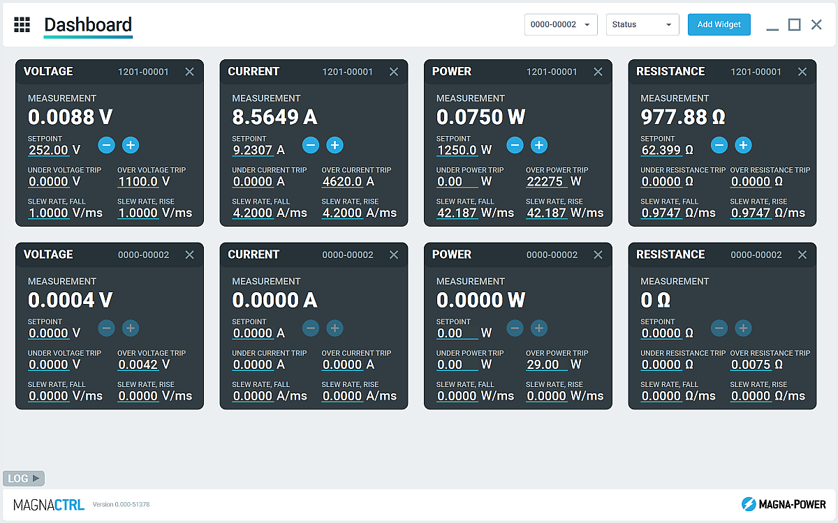
MagnaCTRL 소프트웨어 기본 포함
멀티 제품 대시보드 제어, 진단 및 업데이트—즉시 사용 가능.
MagnaCTRL은 xGen 제품에 기본 포함된 최신 멀티 제품 제어 플랫폼입니다. 대시보드를 구성하고, I/O를 설정하며, 업데이트를 실행하고, 심층 진단 기능에 접근할 수 있습니다—모두 하나의 앱에서 가능합니다.
- 구성 가능한 대시보드: 위젯을 추가/배열하여 연결된 여러 장치를 모니터링하고 제어할 수 있습니다.
- Product Explorer: 장치를 자동 감지하고, 연결을 저장하며, 이후 세션에서 자동으로 재연결합니다.
- 외부 사용자 I/O 패널: 26핀 I/O를 매핑하고, 빠른 배포를 위해 핀 맵을 내보내기/가져오기할 수 있습니다.
- 펌웨어/소프트웨어 업데이트: 새 릴리스를 자동으로 감지하며, 필요 시 오프라인에서 수동 업데이트를 수행할 수 있습니다 (Changelog 참조)
- 캘리브레이션 도구: 프로그래밍/측정 게인/오프셋을 조정하고, 안내에 따라 제어 루프 게인을 튜닝할 수 있습니다.
- 데이터 로깅: 시간에 따른 전압, 전류 및 전력 측정값과 설정의 그래픽 출력 및 .csv 로깅
State-of-the-art USA manufacturing with worldwide support

미국 제조
완벽한 품질 관리를 위한 수직 통합 제조.
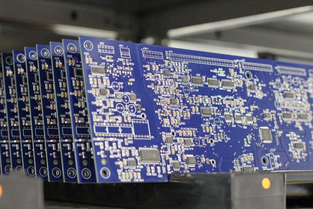
Magna-Power 제품은 뉴저지주 플레밍턴에 위치한 73,500 sq-ft 규모의 본사에서 설계, 제작, 테스트 및 서비스됩니다. 금속 가공, 자성 부품, PCB 조립, 번인 테스트까지 모두 자체적으로 수행하여 품질, 비용, 납기를 철저히 관리합니다.
- 미국 제조: 엔지니어링, 제조, 서비스를 한 지붕 아래에서.
- 자체 생산: 금속 가공, 자성 부품, SMT PCB, 표면 처리.
- 검증된 신뢰성: 모든 제품을 완벽하게 테스트, 교정, 번인 실시.
전 세계 서비스 및 OEM 부품 지원
공장 전문성, 현지 대응.
Magna-Power는 북미, 유럽, 영국, 아시아태평양, 동아시아, 남미 전역의 공장 및 공인 서비스 센터를 통해 자사 제품을 지원하며, 보증 기간 내외를 불문하고 공장 절차와 정품 부품을 사용하여 장비를 원래 사양으로 복원합니다.
- 글로벌 커버리지: 뉴저지 본사 및 지역 공인 서비스 센터.
- 일관된 수리: 공장 진단, 작업 지침서 및 시스템 다이어그램.
- 정품 OEM 부품: 검증된 교체 어셈블리로 예측 가능하고 다운타임이 적은 서비스 제공.
Model Ordering Guide
For both ordering and production, ALx Series models are uniquely defined by several key characteristics, as defined by the following diagram:

ALx Series Models
There are 27 different models in the ALx Series spanning power levels: 1.25 kW, 2.5 kW, 5 kW, 7.5 kW, 10 kW, 12.5 kW, 15 kW, 17.5 kW, 20 kW. To determine the appropriate model:
- Select the desired Max Voltage (Vdc) from the left-most column.
- Select the desired Max Current (Adc) from the same row that contains your desired Max Voltage.
- Construct your model number according to the model ordering guide.
| Model | Max Power kW |
Max Voltage Vdc |
Max Current Adc |
Package Type | Min Voltage Vdc |
Max Resistance Ω |
|---|---|---|---|---|---|---|
| ALx1.25-200-300 | 1.25 | 200 | 300 | Rack-mount | 2.5 | 70.40 |
| ALx1.25-500-125 | 1.25 | 500 | 125 | Rack-mount | 6.0 | 448.00 |
| ALx1.25-1000-37.5 | 1.25 | 1000 | 37.5 | Rack-mount | 7.5 | 1792.00 |
| ALx2.5-200-600 | 2.5 | 200 | 600 | Rack-mount | 2.5 | 70.40 |
| ALx2.5-500-250 | 2.5 | 500 | 250 | Rack-mount | 6.0 | 448.00 |
| ALx2.5-1000-75 | 2.5 | 1000 | 75 | Rack-mount | 7.5 | 1792.00 |
| ALx5-200-1200 | 5 | 200 | 1200 | Floor-standing | 2.5 | 35.20 |
| ALx5-500-500 | 5 | 500 | 500 | Floor-standing | 6.0 | 224.00 |
| ALx5-1000-150 | 5 | 1000 | 150 | Floor-standing | 7.5 | 896.00 |
| ALx7.5-200-1800 | 7.5 | 200 | 1800 | Floor-standing | 2.5 | 23.47 |
| ALx7.5-500-750 | 7.5 | 500 | 750 | Floor-standing | 6.0 | 149.33 |
| ALx7.5-1000-225 | 7.5 | 1000 | 225 | Floor-standing | 7.5 | 597.33 |
| ALx10-200-2400 | 10 | 200 | 2400 | Floor-standing | 2.5 | 17.60 |
| ALx10-500-1000 | 10 | 500 | 1000 | Floor-standing | 6.0 | 112.00 |
| ALx10-1000-300 | 10 | 1000 | 300 | Floor-standing | 7.5 | 448.00 |
| ALx12.5-200-3000 | 12.5 | 200 | 3000 | Floor-standing | 2.5 | 14.08 |
| ALx12.5-500-1250 | 12.5 | 500 | 1250 | Floor-standing | 6.0 | 89.60 |
| ALx12.5-1000-375 | 12.5 | 1000 | 375 | Floor-standing | 7.5 | 358.40 |
| ALx15-200-3600 | 15 | 200 | 3600 | Floor-standing | 2.5 | 11.73 |
| ALx15-500-1500 | 15 | 500 | 1500 | Floor-standing | 6.0 | 74.67 |
| ALx15-1000-450 | 15 | 1000 | 450 | Floor-standing | 7.5 | 298.67 |
| ALx17.5-200-4200 | 17.5 | 200 | 4200 | Floor-standing | 2.5 | 10.06 |
| ALx17.5-500-1750 | 17.5 | 500 | 1750 | Floor-standing | 6.0 | 64.00 |
| ALx17.5-1000-525 | 17.5 | 1000 | 525 | Floor-standing | 7.5 | 256.00 |
| ALx20-200-4800 | 20 | 200 | 4800 | Floor-standing | 2.5 | 8.80 |
| ALx20-500-2000 | 20 | 500 | 2000 | Floor-standing | 6.0 | 56.00 |
| ALx20-1000-600 | 20 | 1000 | 600 | Floor-standing | 7.5 | 224.00 |
Specifications are subject to change without notice. Unless otherwise noted, all specifications measured at the product's maximum ratings.
AC Input Specifications
200-240 Vac (UI2: Universal Input 2); Available on 20 kW Models
Programming Interface Specifications
USB Host (Rear): Type B
RS485 (Rear): RJ-45
MagnaLINK™: RJ-25 x 2
GPIB (Rear): IEEE-488
Referenced to Earth ground; isolated from the DC input
See User Manual for pin layout
Programming Specifications
Current: ±0.2% of full scale current rating
Power: ±0.3% of full scale power rating
Resistance: ±0.3% of full scale resistance rating
Current Mode: 2 ms, 10% to 90% full scale current rating
Power Mode: 100 ms, 10% to 90% full scale power rating
Resistance Mode: 200 ms, 10% to 90% full scale resistance rating
Under Voltage: 0% to 110% of full scale voltage rating
Over Current: 10% to 110% of full scale current rating
Over Power: 10% to 110% of full scale power rating
External User I/O Specifications
Digital Input Impedance: 10 kΩ
Digital Monitoring Voltage: 5V, 32 mA capacity
Digital Reference Voltage: 5V, 20 mA capacity
Analog Programming Voltage: 0-10 V
Analog Programming Resolution: 12-bit, 0.025%
Analog Monitoring Voltage: 0-10 V, 3 mA capacity
Analog Monitoring Impedance: 0.005 Ω
Analog Monitoring Accuracy: 0.05% of full scale
Analog Reference Voltage: 10 V, 20 mA capacity
Physical Specifications
5.25” H x 19” W x 24” D (13.34 x 48.26 x 60.96 cm)
40 lbs (18.1 kg)
5.25” H x 19” W x 24” D (13.34 x 48.26 x 60.96 cm)
65 lbs (29.5 kg)
30.7” H x 24” W x 31.5” D (78.0 x 61.0 x 80.0 cm)
255 lbs (115.7 kg)
30.7” H x 24” W x 31.5” D (78.0 x 61.0 x 80.0 cm)
320 lbs (145.2 kg)
30.7” H x 24” W x 31.5” D (78.0 x 61.0 x 80.0 cm)
385 lbs (174.6 kg)
58.25” H x 24” W x 31.5” D (148.0 x 61.0 x 80.0 cm)
500 lbs (226.8 kg)
58.25” H x 24” W x 31.5” D (148.0 x 61.0 x 80.0 cm)
565 lbs (256.3 kg)
58.25” H x 24” W x 31.5” D (148.0 x 61.0 x 80.0 cm)
630 lbs (285.8 kg)
58.25” H x 24” W x 31.5” D (148.0 x 61.0 x 80.0 cm)
695 lbs (315.3 kg)
Environmental Specifications
Regulatory Specifications
CISPR 22 / EN 55022 Class A
CSA C22.2 No. 61010-1:12; A1:2018
UL 61010-1:Ed.3,2012(R2019)
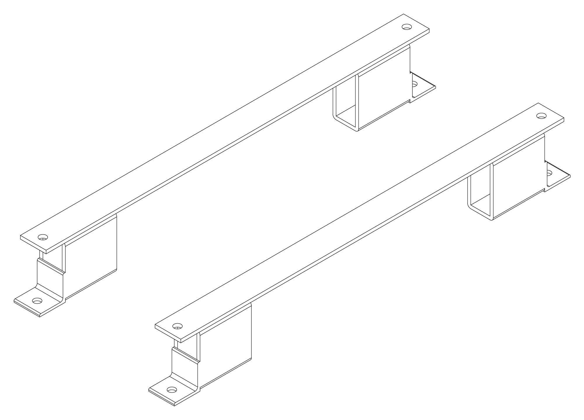
The following are vectorized diagrams for the ALx Series. Refer to the Downloads section for downloadable drawings.


Integrated Options
Standard integrated options are available for Magna-Power products, allowing the product's performance and communication interfaces to be tailors to the specific application.
- Option
- +CAN
- Option
- +ECAT
- Option
- +EIP
- Option
- +LXI

- Option
- +MTCP
Accessories
External accessories and integration services available for this product.