


Slew rate and the available configurations
Slew rate defines the maximum rate of change of output voltage or output current per unit time. It characterizes the power supply's rise and fall times in response to a programmed setpoint change. Slew rate is distinct from transient response, which characterizes the supply's much faster reaction to a step load change at the output terminals.
Because Magna-Power applies a limit on slew rate, the resulting rise time follows a first-order exponential — not a linear ramp. This behavior is consistent across all MagnaDC product families and is governed by the output stage configuration.
Standard Output vs. High Slew Rate (+HS) Option
Magna-Power offers two output stage configurations for its MagnaDC programmable DC power supplies: Standard and High Slew Rate (+HS).
Standard Output
The standard output stage is designed to deliver the lowest achievable output ripple voltage within the constraints of available components, size, and cost. The output filter includes a bank of aluminum electrolytic capacitors selected for their favorable ESR and capacitance characteristics. This configuration produces a well-damped, low-ripple output suitable for the majority of DC power supply applications.
High Slew Rate (+HS) Option
For applications where fast rise and fall times take priority over output ripple performance, the +HS option replaces the standard capacitor bank with a combination of low-capacitance film and aluminum electrolytic capacitors. The reduced output capacitance enables significantly faster voltage and current transitions.
Trade-offs. The +HS option achieves faster slew rates at the expense of higher output ripple voltage. The lower output capacitance also results in a less critically damped response, which can produce voltage overshoots — particularly under light-load or no-load conditions. For applications sensitive to ripple or overshoot, the standard configuration is recommended.
The +HS option must be installed at the factory, preferably at the time of order. Upgrades are available for units already in the field, but require the supply to be returned to the factory.
Slew Rate Specifications
Table 1 summarizes the slew rate time constants for each configuration. These values represent first-order time constants, assuming a fully resistive load.
| Standard | +HS Option | |
|---|---|---|
| Voltage Slew Rate | 170 ms | 5 ms |
| Current Slew Rate | 200 ms | 10 ms |
The specified slew rates apply uniformly to any programmed transition, for example, 0 to 50% of full scale or 0 to 100% of full scale. The time-domain response of voltage or current can be modeled with Equation 1:
where `V(t)` is the voltage at a particular time, `V0` is the commanded output voltage, `t` is time, and `T` is the first order time constant (Magna-Power's slew rate specification) in seconds.
Startup Delay and Soft Start Behavior
When a MagnaDC power supply transitions from standby to power mode via the Start button, the unit executes a soft start sequence before the output becomes active. During this sequence, the front-end pre-charges its DC bus through contactors, limiting inrush current to within the maximum input current rating of the supply. This pre-charge stage introduces a delay before the output begins to respond, resulting in an apparent rise time that is significantly slower than the slew rate specification.
This startup delay is a one-time event that occurs each time the supply transitions from standby to power mode. It does not reflect the steady-state slew rate performance of the unit.
To observe the specified slew rate without the soft start delay, start the supply with both the voltage and current setpoints at 0 Vdc and 0 Adc. With these settings, the output will remain at zero — no voltage or current is delivered. Once the unit is in power mode, program the desired voltage and current setpoints. The resulting output transition will follow the slew rate defined in the specifications.
Experimental Verification
To illustrate the +HS slew rate in practice, a TSD600-24/208+HS was connected to a fully resistive load and commanded to its full-scale output: 600 Vdc at 24 Adc. The results are shown in Figure 1, where the yellow trace is output voltage and the blue trace is output current. The relative performance shown is representative of all MagnaDC models equipped with the +HS option.
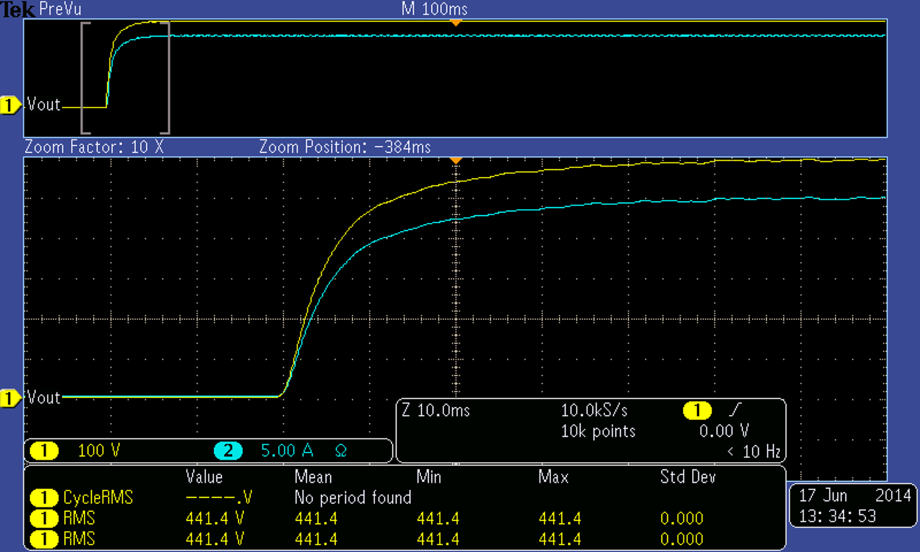
The new setpoints were issued at −20 ms relative to the origin. To verify agreement with Equation 1, consider the output voltage at t = 10 ms after the ramp begins. Substituting V₀ = 600 Vdc, t = 0.010 s, and τ = 0.004 s (5 ms voltage slew rate with +HS) into Equation 1: