


태양광 에뮬레이션 및 인버터 테스트
개요
태양광 어레이는 온도와 일사량의 함수로 변하는 비선형 특성을 가진 DC 출력을 생성합니다. 태양광 인버터와 같이 태양광 어레이에 직접 연결된 장치는 이러한 변화를 고려하여 어레이의 출력을 특성화하고 변환되는 전력량을 극대화합니다. 태양광 어레이의 출력 특성은 표준 DC 전원공급장치와 크게 다르므로, 이러한 테스트 요구사항을 충족하기 위해 DC 전원공급장치에 추가적인 제어 기능을 구현해야 합니다.
태양광 어레이 특성
태양광 어레이의 전압 및 전류 특성은 패널의 온도와 일사량에 따라 변동하며, 대략적으로 일사량은 출력 전류에, 온도는 출력 전압에 영향을 미칩니다. 태양광 인버터와 같은 태양광 어레이 연결 장치는 최대 동작점을 찾아 태양광 어레이의 전력 출력을 극대화해야 합니다. 또한, 최대 전력점 추적 기능이 장착된 장치는 온도와 일조량의 변동을 고려하여 동작점을 조정해야 합니다.
Magna-Power Electronics를 선택하는 이유
- 태양광 어레이 에뮬레이션 또는 표준 전원공급장치: Magna-Power Electronics Photovoltaic Power Profile Emulation 소프트웨어는 모든 Magna-Power Electronics 전원공급장치가 태양광 어레이의 비선형 특성을 에뮬레이션하고 이러한 특성을 시간의 함수로 변화시킬 수 있도록 합니다. 모든 Magna-Power Electronics 전원공급장치는 CV 및 CC 모드의 표준 전원공급장치 동작과 태양광 에뮬레이션 동작 사이를 자유롭게 전환할 수 있습니다. 이러한 이중 동작 기능은 다양한 응용 분야에서 테스트 장비의 활용도를 극대화합니다.
- 정밀한 프로그래밍 및 측정: Magna-Power Electronics의 프로그래밍 및 측정 정확도는 업계 최고 수준입니다. 엔지니어는 교정을 위해 전원공급장치의 측정값을 직접 활용할 수 있어, 테스트 환경에서 계측 장비와 복잡성을 줄일 수 있습니다.
- 고조파 중화: Magna-Power Electronics는 고조파 중화 기술을 선도하여, 전원공급장치가 생성하는 최대 48펄스 파형으로 수 메가와트급 중앙 인버터 테스트를 가능하게 합니다.
- 고속 슬루율 옵션 (+HS): 모든 Magna-Power Electronics 제품에 적용 가능한 고속 슬루율 옵션은 출력 커패시턴스를 줄이고 표준 알루미늄 전해 커패시터 대신 필름 커패시터 기술을 사용합니다. 태양광 인버터 테스트에서 고속 슬루율 옵션은 매우 권장되며, 출력 커패시턴스 감소로 인버터 리플 성분과의 상호작용이 줄어들고 전원공급장치의 대역폭이 향상됩니다.
태양광 어레이 에뮬레이션 소프트웨어
Magna-Power Electronics Photovoltaic Power Profile Emulation (PPPE) 소프트웨어는 EN50530 표준에 기반한 비선형 전압/전류(V/I) 프로파일을 생성하여, 온도와 일조량의 함수로 이러한 V/I 특성을 변화시킬 수 있습니다. 이러한 프로파일을 전원공급장치에 순차적으로 전송하여 사용자가 정의한 간격에 따라 태양광 파라미터의 변화가 전원공급장치의 출력 특성을 변경할 수 있습니다. 또한, 보간 기능을 통해 곡선 간 자동 프로파일 생성이 가능하여 한 온도 및 일사량 조건에서 다른 조건으로 부드럽게 전환할 수 있습니다. 예를 들어, 이 기능은 흐린 겨울 조건에서 맑은 여름 조건으로의 전환을 시뮬레이션하는 데 사용할 수 있습니다. 또는 컴퓨터와 연결이 끊어진 상태에서 사용할 수 있도록 프로파일을 전원공급장치에 내부적으로 저장할 수도 있습니다. 또한, LabVIEW나 Visual Studio와 같은 자동화 환경에서 PPPE의 간편한 태양광 프로파일 생성 기능을 활용할 수 있도록 명령 내보내기 기능을 제공합니다.
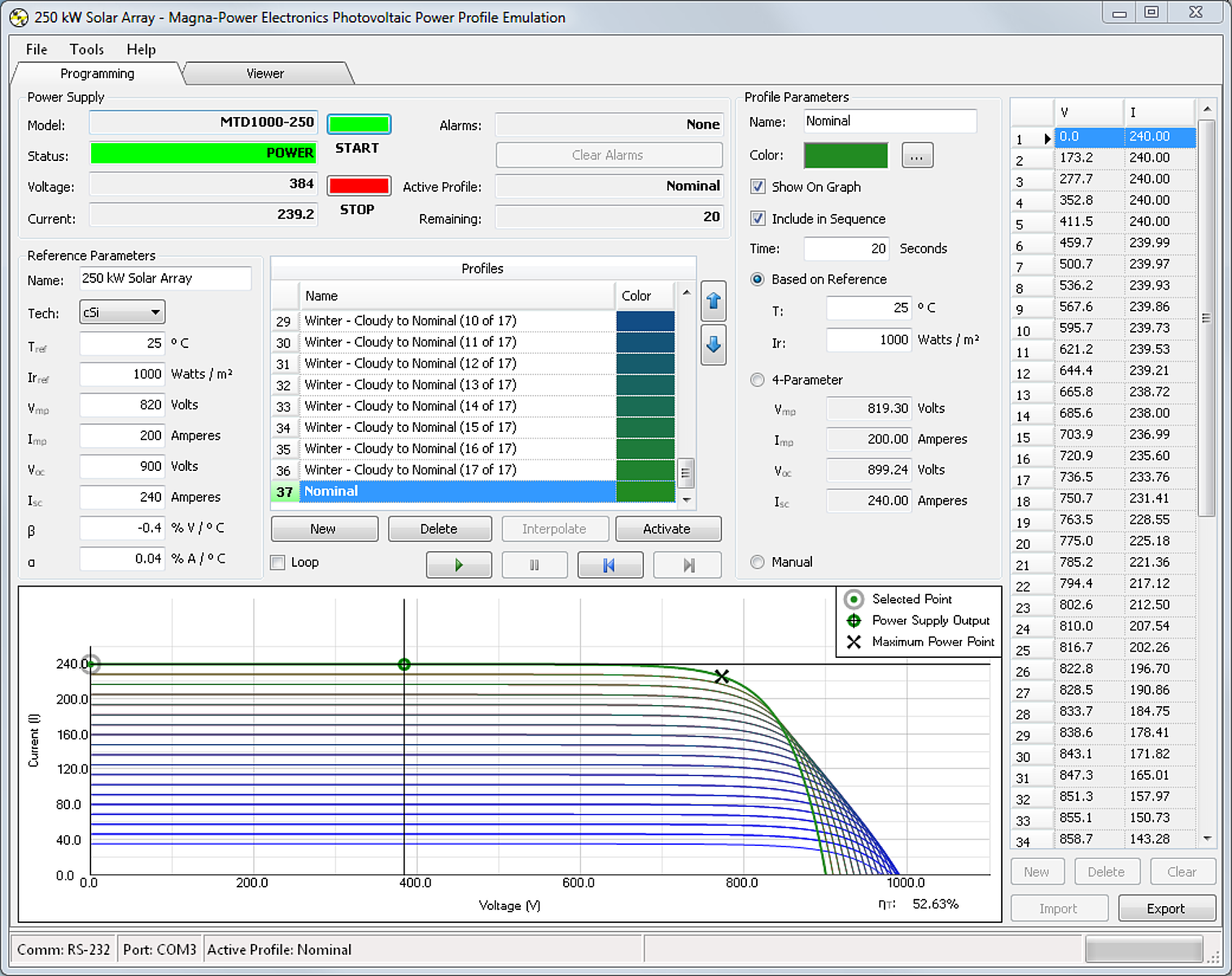
프로파일 생성을 위한 세 가지 방법이 제공됩니다:
- 기준 파라미터: 기준 태양전지 및 어레이 특성이 알려진 경우, 태양전지 파라미터 값 Tref, Irref, Vmp, Imp, Voc, Isc, β, α를 사용하여 프로파일을 생성할 수 있습니다. EN50530 표준에 따라 β 및 α 값을 자동으로 채울 수 있도록 다결정 실리콘(cSi) 또는 박막 기술을 선택하는 드롭다운이 제공됩니다. 기준값을 입력한 후에는 각 새 곡선에 대해 온도와 일사량 값을 지정하는 것만으로 간단하게 새 곡선을 생성할 수 있습니다.
- 4-파라미터: 가장 간단한 프로파일 생성 방법으로, 최대 전력점, 최대 전압(개방 회로), 최대 전류(단락 회로)인 Vmp, Isc, Voc, Isc만으로 프로파일을 생성할 수 있습니다.
- 최대 50개 수동 포인트: PPPE 소프트웨어에서 수동 곡선을 사용할 수 있으며, 전압 및 전류 포인트를 직접 입력하거나 쉼표로 구분된 값(.csv) 파일에서 값을 가져올 수 있습니다. 최대 50개의 포인트를 입력할 수 있으며, 전원공급장치는 동작 중 이러한 포인트 사이에서 구간 선형 근사를 수행하여 높은 해상도를 보장합니다.
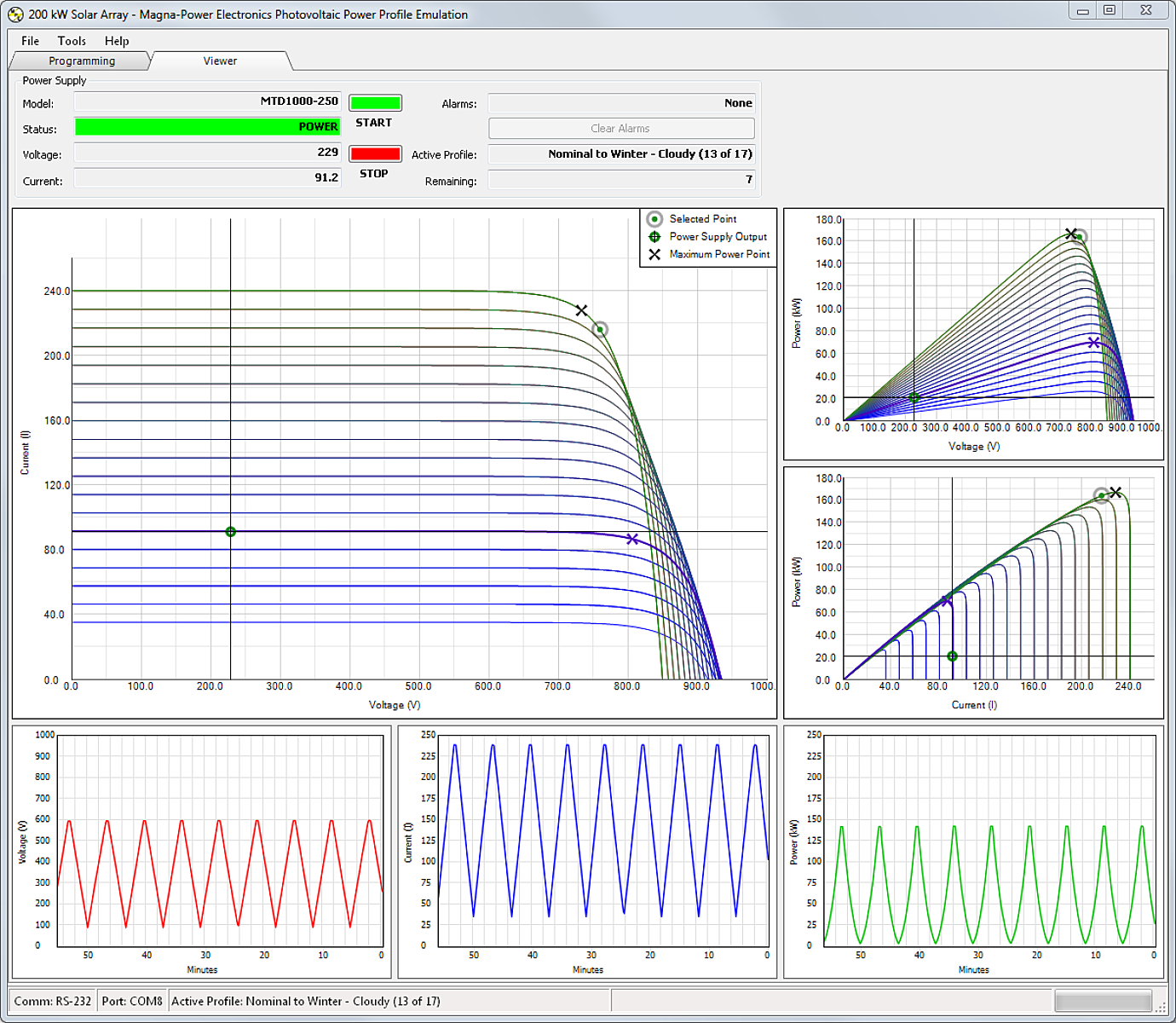
실시간 출력 뷰어는 전압, 전류, 전력 출력을 동시에 표시하는 전체 화면을 제공하며, 시간에 따라 이러한 파라미터를 추적합니다. 이 화면은 연결된 부하가 시간에 따른 온도와 일사량 변화를 추적하는 능력을 명확하게 보여줍니다. 데이터 로깅 기능이 제공되어 출력 전압, 전류, 전력 값과 정의된 출력 특성을 시간에 따라 저장할 수 있습니다.
광범위하고 모듈형인 제품 라인업
Magna-Power Electronics는 태양광 에뮬레이션 기능을 갖춘 업계 최고 범위의 표준 프로그래머블 DC 전원공급장치를 제공합니다. Magna-Power Electronics의 랙마운트 제품은 2 kW부터, 플로어스탠딩 시스템은 최대 4,000 kW까지 제공되며, 전압은 최대 4,000 Vdc(플로팅), 전류는 최대 24,000 Adc입니다. 전체 제품 라인은 동일한 제어 방식과 동일한 프로그래밍 옵션을 갖추고 있습니다. 모든 장치에는 전면 패널 무단계 로터리 제어, RS-232 컴퓨터 인터페이스, 절연된 37핀 아날로그/디지털 외부 제어가 표준으로 제공됩니다. LXI TCP/IP Ethernet (+LXI), IEEE 488.2 GPIB (+GPIB), USB Edgeport (External) (+USB) 등의 추가 프로그래밍 인터페이스 옵션을 사용할 수 있습니다. 모든 프로그래밍 인터페이스는 기본 SCPI 명령 세트를 지원하며 Photovoltaic Power Profile Emulation 소프트웨어와 호환됩니다. 또한, 컴퓨터 기반 전면 패널 제어를 위한 Remote Interface Software와 IVI 드라이버가 포함되어 원격 프로그래밍을 용이하게 합니다. 전력 요구사항이 증가하면 태양광 어레이 에뮬레이터의 전력도 확장할 수 있습니다. Magna-Power Electronics 전원공급장치가 제공하는 모듈형 빌딩 블록을 통해 언제든지 마스터/슬레이브 병렬 또는 직렬로 장치를 추가할 수 있습니다. 최대 유연성을 위해 장치를 개별적으로, 소규모 마스터/슬레이브 시스템으로, 또는 모든 모듈이 동일 모델인 경우 하나의 대규모 시스템으로 함께 사용할 수 있습니다.
중앙 인버터 테스트를 위해 MT Series 제품은 100 kW, 150 kW, 250 kW 모듈 크기로 제공됩니다. 독립형 IGBT 기반 MT Series 장치는 시장에서 가장 큰 표준 스위치모드 전원공급장치 중 하나로, 더 작은 모듈 크기에 비해 스위칭 부품 수를 최소화합니다. 수 메가와트급으로의 확장은 마스터/슬레이브 제어를 제공하는 UID47 장치를 사용하여 수행되며, 하나의 전원공급장치가 나머지 장치를 제어하여 진정한 시스템 동작을 구현합니다.
모든 Magna-Power Electronics 전원공급장치는 동일 정격의 다른 전원공급장치와 마스터/슬레이브 병렬 또는 직렬 동작으로 구성할 수 있습니다. 플러그 & 플레이 마스터/슬레이브 동작은 전원공급장치 간의 제어 신호를 상호 연결하는 UID47 장치를 통해 제공됩니다.
번인 응용에서 중앙 인버터는 높은 전압과 높은 전류를 요구하지만, 동시에 요구하는 경우는 드뭅니다. 따라서, 다양한 직렬 및 병렬 모듈 배열로 재구성할 수 있는 전원공급장치를 보유하는 것이 유리하며, 가장 비용 효율적인 솔루션을 제공합니다. 예를 들어, 2000 Vdc에서 500 Adc, 그리고 500 Vdc에서 2000 Adc의 서로 다른 인버터 번인 요구사항을 고려해 보십시오. 2000 Vdc와 2000 Adc를 모두 충족하는 전원공급장치를 지정하는 대신, Magna-Power Electronics의 모듈형 구성을 사용하여 각기 다른 테스트 요구사항에 맞게 전원공급장치를 직렬에서 병렬 동작으로 변경함으로써 훨씬 더 작고 비용이 적은 솔루션을 지정할 수 있습니다.
전원공급장치의 출력단을 직렬에서 병렬로 재구성하는 것은 외부 접촉기 또는 저가의 스로우 스위치를 통해 수행됩니다. 재구성은 출력이 통전된 상태에서 수행되어서는 안 되며, 전원공급장치는 영 전압 및 영 전류 상태여야 합니다. 또한, 슬레이브 장치가 직렬 또는 병렬 동작에 따라 다른 신호를 수신하므로 UID47 제어 배선도 변경해야 합니다. 이 과정에 대한 모범 사례를 지원하기 위해 Magna-Power Electronics 응용 엔지니어가 도움을 드릴 수 있습니다.
고속 슬루율 옵션 (+HS)
고속 슬루율 옵션은 스위칭 전원공급장치 설계에 내재된 여러 한계를 해결합니다. 급격한 전압 전환은 출력 커패시터를 충전 및 방전하기 위한 에너지를 내부 전자 회로가 공급해야 합니다. 전원공급장치 내부의 피크 전류가 슬루율을 결정하며, 더 적은 커패시턴스를 사용하면 더 짧은 시간 내에 전압 전환이 가능합니다. 또한, 커패시턴스가 적으면 개방 회로 조건에서의 방전 요구사항이 줄어듭니다.
Magna-Power Electronics 전원공급장치의 표준 출력단은 사용 가능한 부품, 크기, 비용의 제약 내에서 가능한 가장 낮은 출력 리플 전압을 제공하도록 설계되었습니다. 출력단의 일부는 이 기능을 제공하는 데 필요한 전기적 특성을 가진 알루미늄 전해 커패시터 뱅크로 구성됩니다. 이러한 부품은 전원공급장치에 부하가 없고 비활성화된 상태에서 전압을 방전하기 위한 블리드 저항기가 필요합니다. 이러한 부품의 존재와 그에 따른 성능은 일반적으로 업계에서 허용되지만, 더 낮은 출력 커패시턴스와 더 낮은 손실의 블리드 저항기가 매우 바람직하고 더 높은 리플 전압이 허용되는 응용 분야가 있습니다. 이러한 요구를 충족하기 위해, 저용량 필름 및 알루미늄 전해 커패시터로 구성된 출력단을 갖춘 고속 슬루율 옵션이 제공됩니다.
태양광 에뮬레이션 응용에서 더 높은 대역폭과 더 낮은 출력 커패시턴스는 고속 최대 전력 추적 알고리즘과 함께 향상된 성능을 가능하게 합니다. 최대 전력 추적 회로는 태양광 어레이의 동작점을 변화시켜 최대 전력 출력을 결정합니다. 알고리즘의 속도가 소스의 속도를 초과할 때 응답이 느린 에뮬레이션 소스는 문제를 야기할 수 있습니다. 또한, 출력 커패시턴스가 낮으면 태양광 인버터 입력을 단락시켜 발생하는 동작점 변화와 과도 현상이 더 낮은 불필요한 입력 전류를 발생시킵니다.
고절연 출력 옵션 (+ISO)
장치를 직렬로 연결할 때, 제품 사양에 따라 제품 시리즈 및 모델에 따라 달라지는 제품의 출력 절연 등급에 유의하는 것이 중요합니다. 직렬로 구성된 전원공급장치 시스템이 제품의 절연 등급을 초과해서는 안 됩니다. 다음 표는 사용 가능한 출력 절연 등급에 대한 빠른 참조를 제공합니다:
| Standard Output Isolation for Models Rated 1000 Vdc and Below, No Option | Output Isolation for Model Rated 250-1000 Vdc With +ISO Option | Standard Output Isolation for Models Rated Above 1000 Vdc, No Option | |
|---|---|---|---|
| XR Series | 1000 Vdc | N/A | N/A |
| TS Series | 1000 Vdc | ±(2000 Vdc + Vo/2) | ±(2000 Vdc + Vo/2) |
| MS Series | 1000 Vdc | ±(2000 Vdc + Vo/2) | ±(2000 Vdc + Vo/2) |
| MT Series | 1000 Vdc | 4000 Vdc | 4000 Vdc |
Note: Vo is the product's output voltage rating
XR Series, TS Series, MS Series 모델의 표준 절연 고절연 옵션(+ISO)은 1000 Vdc 이하의 TS Series 및 MS Series 제품에 사용 가능하며, Vo가 제품의 출력 전압 정격일 때 최대 2000 Vdc + Vo/2의 완전 플로팅 출력 절연을 제공합니다. 400 Vdc 이상의 MT Series 제품에는 4000 Vdc 출력 절연이 제공됩니다.
중앙 인버터 에너지 재생
개발 및 생산용 메가와트급 중앙 인버터는 테스트 장비와 전력 설비에 고유한 요구사항을 부과합니다. 인버터의 AC 출력을 DC 전원공급장치의 입력으로 되돌려 전력 재생을 가능하게 합니다. 태양광 인버터 출력은 일반적으로 DC 전원공급장치의 입력으로 재생되며, 이를 통해 전력 시스템은 전체 전력 변환의 작은 부분인 전체 손실만 공급하도록 정격을 낮출 수 있습니다. 이러한 유형의 구성에서 전력 고조파는 테스트 성능과 신뢰성에 중요한 역할을 합니다.
입력 전류 고조파는 거의 모든 전원공급장치의 부산물입니다. 전압과 전류의 주파수 및 위상이 일치할 때만 부하에 전력이 전달될 수 있습니다. 3상 입력 정류기를 사용하는 3상 전원공급장치의 경우, 입력 전류는 n이 1부터 증가하는 정수일 때 6n±1의 이론적 스펙트럼을 가지며, 이를 6펄스 파형이라 합니다. 이는 3상 입력 정류기를 가진 전원공급장치가 기본 주파수의 1, 5, 7, 11, 13, 17, 19 ... 배의 입력 전류를 생성한다는 것을 의미합니다. 이론적 크기는 고조파 성분의 역수로 감쇠합니다. 제5 및 제7 고조파 성분의 크기는 각각 기본 성분의 20%와 14%입니다.
전력 시스템에서 고조파 전류는 비정상적인 경로를 찾을 수 있으며, 크기가 상당하고 고조파 주파수에 민감한 부하가 있는 경우 문제를 일으킬 수 있습니다. 예를 들어, 조명용 안정기에는 고조파 전류에 의해 여기될 수 있는 직렬 연결된 커패시터와 인덕터가 있습니다. IEEE는 권장 한도를 정의하는 표준인 IEEE 519를 도입했습니다. 이 표준을 구현하려면 전력 시스템과 고조파를 생성하는 기타 부하에 대한 지식이 필요합니다. 안타깝게도 이 표준에서는 동일한 전원공급장치가 한 응용에서는 한도를 초과할 수 있고 다른 응용에서는 그렇지 않을 수 있습니다. 마찬가지로, 전원공급장치는 IEEE 519를 충족하든 충족하지 않든 고조파 관련 문제를 일으킬 수도 있고 일으키지 않을 수도 있습니다. 고조파 문제의 위험을 최소화하는 가장 좋은 솔루션은 소스에서 고조파 전류를 제거하는 것입니다.
Magna-Power Electronics 고조파 중화기는 전력 위상의 수를 증가시켜 고조파 군을 억제합니다. 다수의 전원공급장치가 직렬 또는 병렬로 사용되고 균등하게 부하가 걸릴 때 사용할 수 있습니다. 고조파 중화기는 각각 12n±1, 18n±1, 24n±1 또는 48n±1 차수의 고조파 전류 성분을 가진 12펄스, 18펄스, 24펄스 또는 48펄스 파형을 생성할 수 있습니다. 그림 1은 6펄스와 12펄스 파형 간의 이론적 차이를 보여주며, 18펄스 파형은 유사하지만 더 많은 단계를 가집니다. 그림 2는 그에 따른 스펙트럼 차이를 보여줍니다. HN Series 고조파 중화기는 적절한 크기의 회로 차단기로 보호됩니다.
모든 250 kW MT Series 제품에는 통합 12펄스 고조파 중화기가 포함되어, 250 kW 소스는 표준으로 12펄스 AC 파형을 생성합니다. 더 높은 전력 수준에 도달하기 위해 여러 250 kW MT Series 장치가 UID47 장치를 사용하여 마스터/슬레이브 병렬 및/또는 직렬로 연결됩니다. 수 메가와트급 중앙 인버터를 위해 Magna-Power Electronics는 가장 까다로운 고조파 요구사항도 충족할 수 있는 500 kW 24펄스 고조파 중화기 HN500 또는 48펄스 고조파 중화기 HN1000을 제공합니다. 이 옵션이 대형 MT Series 시스템에 공급될 때, HN500 장치 1대는 250 kW 전원공급장치 2대마다, HN1000 1대는 250 kW 전원공급장치 4대마다 사용됩니다. 수전 AC 전력은 단일 진입점으로 HN500/HN1000의 1차측에 공급됩니다. HN500/HN1000의 2차측에서 전원공급장치의 AC 입력까지의 케이블링은 Magna-Power Electronics에서 제공합니다.
요약
Magna-Power Electronics는 태양광 인버터 테스트 요구사항을 위한 광범위한 솔루션을 제공합니다. Photovoltaic Power Profile Emulation 소프트웨어는 EN50530 표준에 따른 비선형 V/I 곡선 생성, 데이터 로깅, Magna-Power Electronics 전원공급장치를 통한 순차적 곡선 에뮬레이션을 제공합니다. 고속 슬루율 출력(+HS) 및 고절연 출력(+ISO)과 같은 옵션은 특정 태양광 인버터 테스트 요구사항에 맞는 출력 업그레이드를 제공합니다. 마지막으로, Magna-Power Electronics의 혁신적인 고조파 중화 기술은 수 메가와트급에서 스위치모드 전원공급장치 기술을 활용하면서도 깨끗한 AC 파형을 구현합니다.