


Producto accesorio
Universal Interface Device
Configuración maestro-esclavo de alto rendimiento, play & play
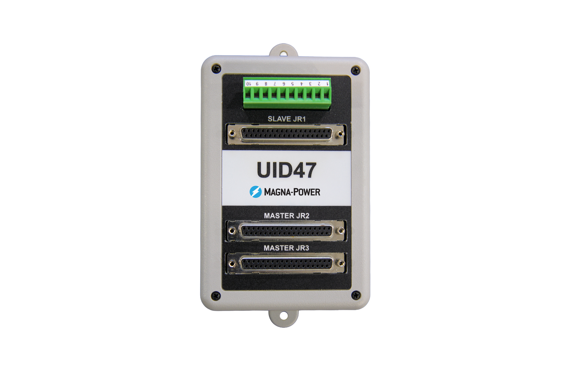
El Universal Interface Device 47 (UID47) fue diseñado para simplificar en gran medida el proceso de configuración maestro-esclavo de fuentes de alimentación de CC programables MagnaDC. El dispositivo contiene los cables de comunicación D-Sub, conectores y circuitos necesarios para configurar las fuentes de alimentación de CC de Magna-Power en operación paralela maestro-esclavo o en serie maestro-esclavo. La operación paralela maestro-esclavo permite que dos o más fuentes de alimentación compartan equitativamente la corriente de salida cuando se conectan entre sí. La operación en serie maestro-esclavo permite que dos o más fuentes de alimentación compartan equitativamente el voltaje de salida cuando se conectan entre sí.
Un conector de derivación adicional de 37 pines en el UID47 se mapea directamente a la fuente de alimentación maestra, lo que permite que un sistema maestro-esclavo siga siendo controlado y monitoreado mediante E/S analógica-digital del usuario. El UID47 también contiene un área en la placa de circuito impreso para interconectar cables y colocar componentes para aplicaciones específicas del usuario, que pueden vincularse a un conector de derivación de 10 pines para el usuario..

| SKU | Precio | Cantidad |
|---|---|---|
| UID46 | ||
| UID47 | ||
| UID53 |

Hable con un experto
Programar una llamada con Magna-Power
Elija un horario que le convenga, opcionalmente agregue algunos colegas y luego reciba una invitación a la llamada con un enlace por correo electrónico para discutir su requerimiento con los ingenieros de aplicaciones de Magna-Power.
Choose Your UID
One UID is required for every slave power supply in the system.
UID46: Analog Reference Control
The UID46 drives slave units through their 0-10 V external analog references, using the master's own monitor signals as the set point source. This method tightly matches output sharing between units, making the UID46 the recommended choice for current mode control applications and for high-current systems — such as large electromagnet and superconducting magnet loads — where current imbalance between units must be minimized. In current mode control, transient response is identical to the UID47 and UID53.
Includes: UID46, qty (2) 6-ft 37-conductor shielded cables
UID47: Gate Driver Control
The UID47 configures the master power supply to directly control the gate drivers of its slave units. With a single control loop commanding every unit, the UID47 delivers the fastest transient response performance, making it the general-purpose choice for most master/slave systems.
Includes: UID47, qty (2) 6-ft 37-conductor shielded cables
UID53: Gate Driver Control + BDx/DBx Module Breakout
The UID53 provides everything in the UID47, plus a dedicated 37-pin breakout connector (JR5) that carries the power supply interface signals required by Magna-Power's BDx and DBx Modules. In a master/slave system the power supply's user I/O connector is occupied by the UID cable — the UID53's breakout and included 37-pin to 15-pin interface cable let a BDx or DBx Module integrate with the power supply while it remains part of the master/slave configuration.
Includes: UID53, qty (2) 6-ft 37-conductor shielded cables, 37-pin to 15-pin module interface cable
Model Comparison
| UID46 | UID47 | UID53 | |
|---|---|---|---|
| Master/slave control method | Analog reference programming (0-10 V) | Direct gate driver control | Direct gate driver control |
| Transient response | Same as UID47/UID53 in current mode control; slower in voltage mode control | Fast, single control loop | Fast, single control loop |
| Parallel current sharing | Tightly matched between units | Total current as programmed; division between units may vary up to 5% of full scale | Total current as programmed; division between units may vary up to 5% of full scale |
| BDx/DBx Module breakout | — | — | Yes |
| Custom user circuitry pad area | Yes | Yes | Yes |
| Best suited for | Current mode control applications or high current systems where current imbalance between units must be minimized | General purpose master/slave operation | Master/slave systems integrating a BDx or DBx Module |
In every configuration, the total output of the system matches the programmed value; a two-unit parallel system delivers twice the current programmed on the master. The comparison above describes only how that total divides between units.
How It Works

Parallel operation connects two or more power supplies for a total output current equal to the sum of the individual units, with equal current sharing under all load conditions and complete control from the master.

Series operation connects two or more power supplies for a total output voltage equal to the sum of the individual units, with equal voltage sharing under all load conditions.
Systems scale to three or more supplies by daisy-chaining additional UID units, so master control and monitoring signals route automatically to every slave. Each UID ships factory-configured for parallel operation; switching to series requires only moving the internal jumper.
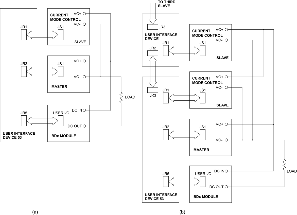
BDx/DBx Module integration (UID53): blocking diode and high-stability modules connect directly to the UID53's breakout connector, preserving full module protection features, including power supply shutdown on module thermal alarm, inside a master/slave system.
Custom Configurations

Every UID doubles as a development platform for custom control and monitoring. All 37 power supply interface signals are broken out to labeled pad areas on the printed circuit board, a 10-position screw-terminal connector provides user-defined external connections, and a general-purpose prototyping area in the center of the board accepts user components, for example, OR'ing diodes to combine multiple diagnostic alarm signals into a single output.
Las especificaciones están sujetas a cambios sin previo aviso. Salvo que se indique lo contrario, todas las especificaciones se miden en los valores nominales máximos del producto.