



Produit accessoire
Universal Interface Device
Couplage maître-esclave haute performance, prêt à l'emploi
Le dispositif d'interface universel 47 (UID47) a été conçu pour simplifier considérablement le processus de couplage maître-esclave des alimentations DC programmables MagnaDC. Le dispositif contient les câbles de communication D-Sub, les connecteurs et les circuits nécessaires à la configuration des alimentations DC Magna-Power en mode maître-esclave parallèle ou série. Le mode maître-esclave parallèle permet à deux alimentations ou plus de partager équitablement le courant de sortie lorsqu'elles sont connectées ensemble. Le mode maître-esclave série permet à deux alimentations ou plus de partager équitablement la tension de sortie lorsqu'elles sont connectées ensemble.
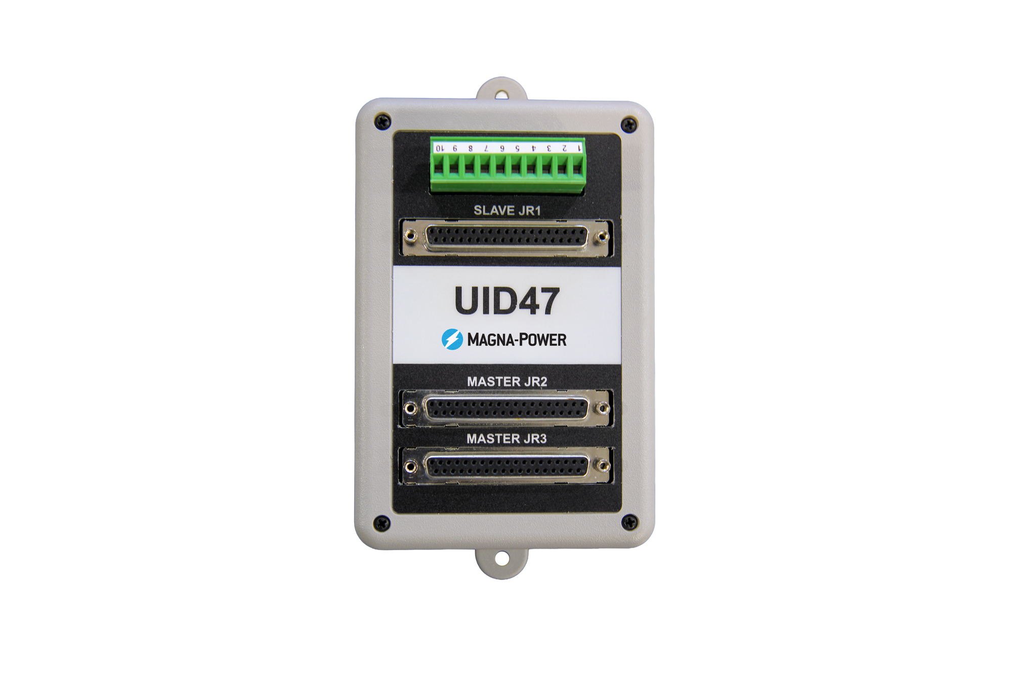
Un connecteur de dérivation supplémentaire à 37 broches sur le UID47 est directement relié à l'alimentation maître, permettant à un système maître-esclave d'être toujours contrôlé et surveillé via les E/S utilisateur analogiques-numériques. Le UID47 contient également une zone sur le circuit imprimé pour l'interconnexion de fils et la mise en place de composants destinés à des applications utilisateur spécifiques, pouvant être reliée à un connecteur de dérivation utilisateur à 10 broches..
| SKU | Description | Prix | Quantité |
|---|---|---|---|
| UID46 | UID46 | ||
| UID47 | UID47 | ||
| UID53 | UID53 |

Parlez à un expert
Choose Your UID
One UID is required for every slave power supply in the system.
UID46 — Analog Reference Control
[IMAGE: diagram_uid46_enclosure.eps]
The UID46 drives slave units through their 0-10 V external analog references, using the master's own monitor signals as the set point source. This method tightly matches output sharing between units, making the UID46 the recommended choice for current mode control applications and for high-current systems — such as large electromagnet and superconducting magnet loads — where current imbalance between units must be minimized. In current mode control, transient response is identical to the UID47 and UID53.
Includes: UID46, qty (2) 6-ft 37-conductor shielded cables[ADD TO CART — UID46]
UID47 — Gate Driver Control
[IMAGE: diagram_uid47_enclosure.eps]
The UID47 configures the master power supply to directly control the gate drivers of its slave units. With a single control loop commanding every unit, the UID47 delivers the fastest transient response performance, making it the general-purpose choice for most master/slave systems.
Includes: UID47, qty (2) 6-ft 37-conductor shielded cables[ADD TO CART — UID47]
UID53 — Gate Driver Control + BDx/DBx Module Breakout
[IMAGE: diagram_uid53_enclosure.eps]
The UID53 provides everything in the UID47, plus a dedicated 37-pin breakout connector (JR5) that carries the power supply interface signals required by Magna-Power's BDx and DBx Modules. In a master/slave system the power supply's user I/O connector is occupied by the UID cable — the UID53's breakout and included 37-pin to 15-pin interface cable let a BDx or DBx Module integrate with the power supply while it remains part of the master/slave configuration.
Includes: UID53, qty (2) 6-ft 37-conductor shielded cables, 37-pin to 15-pin module interface cable[ADD TO CART — UID53]
Model Comparison
| UID46 | UID47 | UID53 | |
|---|---|---|---|
| Master/slave control method | Analog reference programming (0-10 V) | Direct gate driver control | Direct gate driver control |
| Transient response | Same as UID47/UID53 in current mode control; slower in voltage mode control | Fast, single control loop | Fast, single control loop |
| Parallel current sharing | Tightly matched between units | Total current as programmed; division between units may vary up to 5% of full scale | Total current as programmed; division between units may vary up to 5% of full scale |
| BDx/DBx Module breakout | — | — | Yes |
| Custom user circuitry pad area | Yes | Yes | Yes |
| Best suited for | Current mode control applications or high current systems where current imbalance between units must be minimized | General purpose master/slave operation | Master/slave systems integrating a BDx or DBx Module |
In every configuration, the total output of the system matches the programmed value; a two-unit parallel system delivers twice the current programmed on the master. The comparison above describes only how that total divides between units.

Parallel operation connects two or more power supplies for a total output current equal to the sum of the individual units, with equal current sharing under all load conditions and complete control from the master.

Series operation connects two or more power supplies for a total output voltage equal to the sum of the individual units, with equal voltage sharing under all load conditions.
Systems scale to three or more supplies by daisy-chaining additional UID units, so master control and monitoring signals route automatically to every slave. Each UID ships factory-configured for parallel operation; switching to series requires only moving the internal jumper.
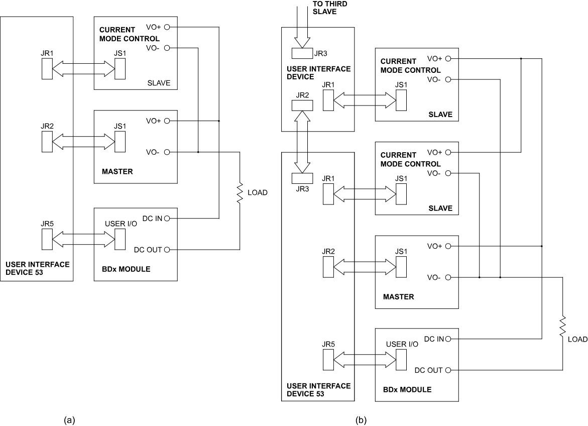
BDx/DBx Module integration (UID53): blocking diode and high-stability modules connect directly to the UID53's breakout connector, preserving full module protection features, including power supply shutdown on module thermal alarm, inside a master/slave system.

Every UID doubles as a development platform for custom control and monitoring. All 37 power supply interface signals are broken out to labeled pad areas on the printed circuit board, a 10-position screw-terminal connector provides user-defined external connections, and a general-purpose prototyping area in the center of the board accepts user components, for example, OR'ing diodes to combine multiple diagnostic alarm signals into a single output.
Les spécifications sont susceptibles d'être modifiées sans préavis. Sauf indication contraire, toutes les spécifications sont mesurées aux valeurs nominales maximales du produit.