




Test à double impulsion pour SiC et GaN : l'alimentation haute tension du bus DC
Sélection d'une alimentation DC pour le test à double impulsion (DPT) des semiconducteurs à large bande interdite SiC et GaN, avec exemples pratiques et recommandations sur la tension, le courant, la programmabilité et les exigences de sécurité.
From Curve Tracers to Nanosecond Transitions
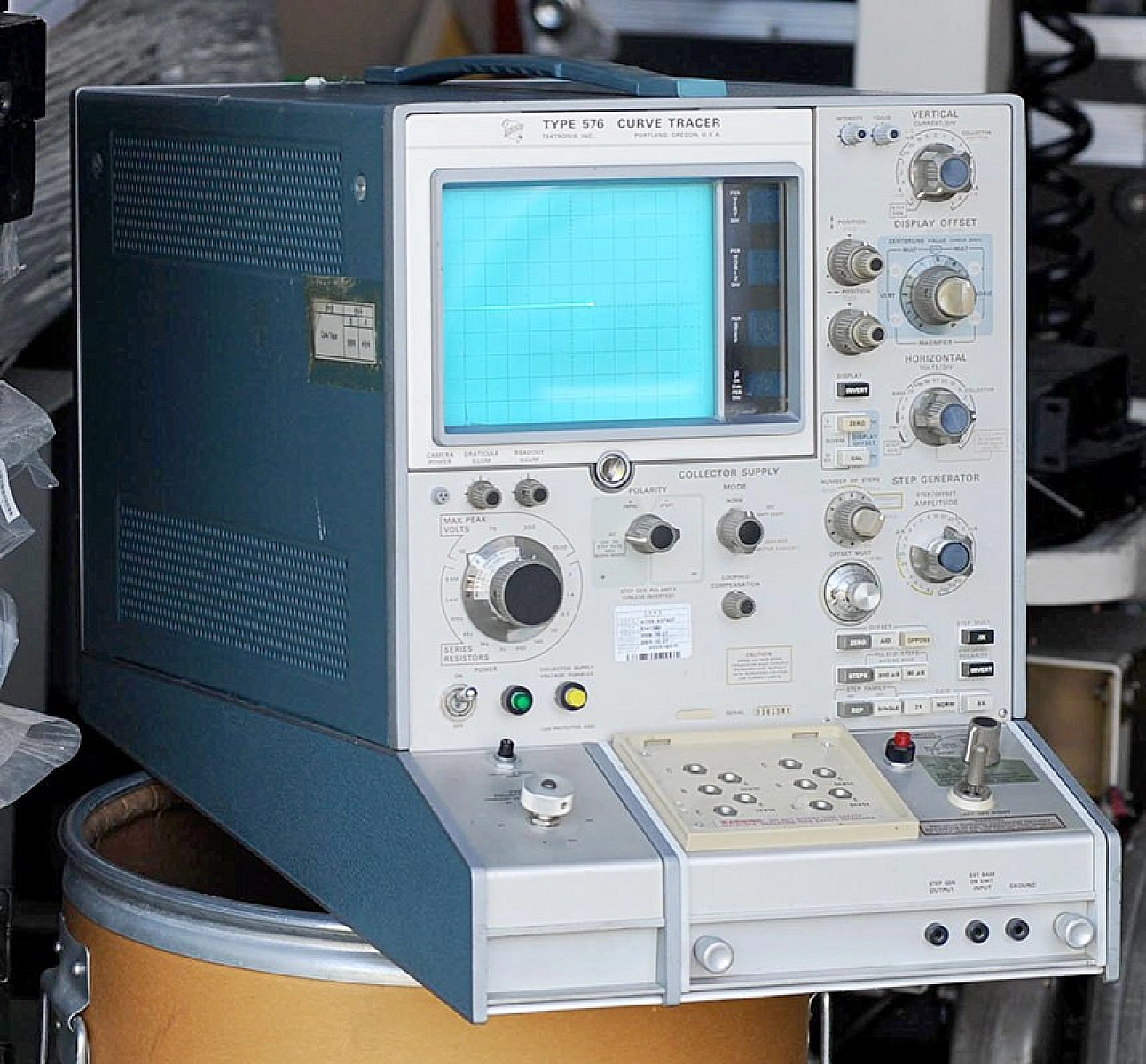
For most of the history of power semiconductor characterization, the workhorse instrument sat quietly in the corner of the lab: the curve tracer. Tektronix introduced the first commercial curve tracer in 1955, and the legendary Type 576, introduced in 1969 and capable of sweeping 1500 volts and 20 amperes through a device under, defined how a generation of power engineers understood transistors, diodes, thyristors, and IGBTs. The 576 and its successors, the 370A/B series, remained in production into the mid-1980s and are still in active use today for failure analysis and teaching.
Curve tracers are fundamentally steady-state instruments. They sweep a voltage, measure the resulting current, and plot the I-V characteristic on a screen. For silicon MOSFETs and IGBTs switching at tens of kilohertz in yesterday’s power electronics, that was enough.
That era ended with the commercial emergence of silicon carbide (SiC) and gallium nitride (GaN) power devices. Wide bandgap (WBG) semiconductors switch at rates that turn switching loss into the dominant loss mechanism. The parameters that determine system efficiency — turn-on energy (Eon), turn-off energy (Eoff), reverse recovery energy (Err), voltage overshoot, dv/dt, di/dt — live entirely in the dynamic behavior of the device during nanosecond transitions. A curve tracer cannot see them.
The industry’s answer is the Double Pulse Test (DPT), codified in JEDEC JEP182 and the IEC 60747-8/-9 standards. DPT is now a required step in datasheet generation, converter design validation, and production-line characterization at every serious power semiconductor manufacturer.
This application note covers the fundamentals of DPT briefly, then focuses on the element most often glossed over in DPT discussions: the DC bus supply that anchors every setup, and the specific engineering decisions that go into selecting one correctly.
What DPT Measures
A double pulse test extracts the dynamic switching parameters that datasheets rely on and converter designs depend on:
- Turn-on: turn-on delay (td,on), rise time (tr), turn-on energy (Eon), dv/dt, di/dt
- Turn-off: turn-off delay (td,off), fall time (tf), turn-off energy (Eoff), dv/dt, di/dt
- Reverse recovery (of the freewheeling device): reverse recovery time (trr), peak reverse recovery current (Irr), reverse recovery charge (Qrr), reverse recovery energy (Err)
These parameters feed directly into converter efficiency calculations, thermal modeling, EMI prediction, and gate drive optimization, which is why every WBG device datasheet publishes them, and why every converter designer wants to verify them on the specific parts they’re buying.
How Double Pulse Testing Works
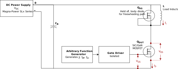
The canonical DPT circuit is a half-bridge with an inductive load. The device under test is typically the low-side switch. The high-side device, often another MOSFET with its body diode, or a dedicated freewheeling diode, provides the current path during the freewheeling interval. A large DC-link capacitor bank supplies the pulsed energy, and a DC power supply charges the bank to the test voltage.
The three phases
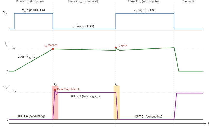
A double pulse test, despite its name, has three distinct intervals.
Phase 1: Charging pulse (τc)
The DUT turns on. Current ramps up linearly in the load inductor according to:
Les trois phases
Un test à double impulsion, malgré son nom, comporte trois intervalles distincts.
Phase 1 : Impulsion de charge (τc)
Le DUT s'active. Le courant augmente linéairement dans l'inductance de charge selon :
La largeur de la première impulsion τc est choisie pour atteindre le courant de test cible Itest :
At the end of this interval, the DUT turns off. This is where the first turn-off event is captured — at the target test current, with the DC bus fully charged. This is the Eoff measurement.
Phase 2: Pulse break (τoff)
The DUT is off. Inductor current circulates through the high-side freewheeling device. This interval must be long enough for switching transients to fully decay, but short enough that inductor current doesn’t drop significantly.
Phase 3 Second pulse (τon)
The DUT turns on again. Now the turn-on event is captured at the target current, with realistic di/dt conditions. Simultaneously, the freewheeling device undergoes reverse recovery, which is captured as the peak Irr spike. This is where Eon and Err are measured.
Pertes de commutation et dimensionnement du banc de condensateurs
Les pertes de commutation sont calculées en intégrant le produit de la tension instantanée et du courant à travers la transition. Pour la mise en conduction :
Eoff and Err follow the same form over their respective intervals. Integration limits are defined by JEDEC JEP182, typically at 10% voltage and current crossing thresholds. Modern oscilloscopes with DPT application software automate the calculation.
The DC-link capacitor bank must be large enough that the bus voltage stays substantially constant during the pulse. From energy balance, with small allowable droop ΔVDC:
Les configurations DPT pratiques utilisent de quelques dizaines à plusieurs milliers de microfarads de capacité film en parallèle, disposés de manière à minimiser l'inductance série équivalente. Le dimensionnement de ce banc de condensateurs devient également une donnée d'entrée pour le calcul de sélection de l'alimentation.
Le paysage commercial : trois approches pour construire un banc DPT
L'industrie s'est organisée autour de trois grandes catégories de configuration DPT.
Systèmes clés en main
Ensembles entièrement intégrés fournis par le fabricant, comprenant driver de grille, montage, mesure, logiciel d'analyse, et parfois l'alimentation du bus DC. Exemples : Keysight PD1500A, Rohde & Schwarz + PE-Systems avec l'oscilloscope R&S MXO. Résultats rapides et conformité JEDEC immédiate, mais avec des enveloppes de tension et de courant fixes et un coût d'investissement élevé.
Ensembles d'instruments
Un oscilloscope à large bande passante associé à un générateur de fonctions arbitraires, des sondes spécialisées et une option logicielle DPT. L'exemple canonique est le MSO série 4/5/6 B de Tektronix avec l'application WBG-DPT et l'AFG31000 ; Teledyne LeCroy avec sondes isolées optiques en est un autre. Coût inférieur aux systèmes clés en main, et les instruments restent utilisables pour d'autres travaux, mais le montage, le driver de grille, le banc de condensateurs, l'inductance de charge et l'alimentation DC restent à la charge de l'utilisateur.
Bancs d'essai personnalisés / DIY
Dominants chez les fabricants de semi-conducteurs, les laboratoires de recherche et les équipementiers repoussant les limites en tension et en courant des composants. Chaque élément est sélectionné individuellement pour correspondre à l'enveloppe de test visée. C'est la seule voie pour les composants au-delà de 1700 V, les modules à fort courant (de plusieurs centaines d'ampères au kiloampère) et les structures de composants innovantes pour lesquelles les conditions de test ne sont pas encore normalisées.
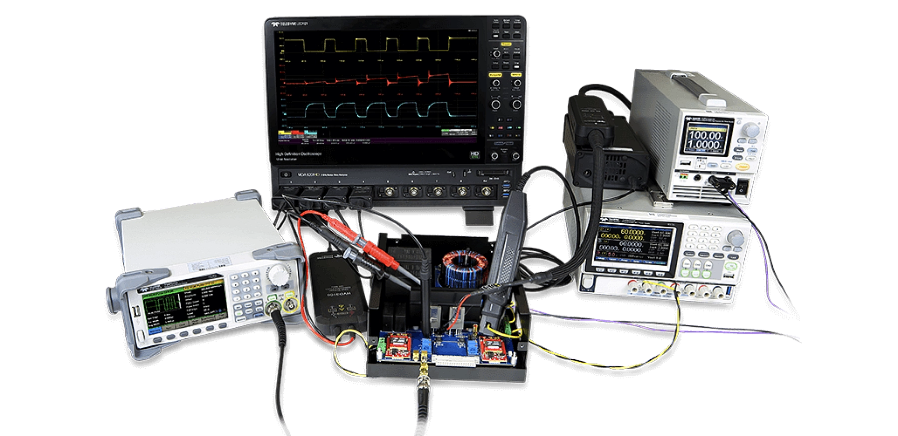
The constant across all three architectures is the DC bus supply. Every system treats it as a given. The rest of this application note covers what it actually takes to specify one correctly.
Power Supply Selection for DPT
The DC power supply in a DPT bench performs a specific and often misunderstood role. It does not source the pulsed current into the DUT directly, that energy comes from the DC-link capacitor bank. The supply’s job is to charge the capacitor bank to the test voltage and recharge it between shots, while doing so accurately, repeatably, safely, and under automated control.
That role carries specific requirements.
Voltage rating
The supply must deliver the DC bus voltage at which characterization is performed. Good practice tests WBG devices at 50–80% of their rated VDS. Practical implications:
| Device rating | Typical DPT bus voltage | Supply rating |
|---|---|---|
| 650 V GaN e-HEMT | 400 V | 500 V minimum |
| 1200 V SiC MOSFET | 800–1000 V | 1000–1500 V |
| 1700 V SiC MOSFET | 1200–1400 V | 1500–2000 V |
| 3300 V SiC module | 2500–2800 V | 3000 V+ |
| 6500 V SiC / high-V devices | 5000+ V | 6000–10000 V |
The trend line is unambiguous: device voltages are climbing. A DPT bench built around a 1500 V supply in 2020 cannot characterize the 3300 V devices entering volume production now.
Current capability and how to size it
This is where DC supply selection is most often misunderstood. The peak pulsed current flowing into the DUT during the test is sourced by the capacitor bank, not the supply. The supply’s job is to replenish the energy drawn from the capacitor bank between shots, equating to a much smaller current requirement for the supply than the peak pulse current.
There are two constraints to evaluate. The binding requirement is whichever is larger.
Energy balance (usually dominant). Each DPT shot transfers energy from the capacitor bank into the load inductor:
Si les tirs sont répétés à une fréquence fshot, la puissance moyenne que l'alimentation doit fournir est :
Le courant minimal de l'alimentation est la puissance moyenne divisée par la tension du bus :
Contrainte de temps de recharge (déterminante à cadences de tir élevées). Le banc de condensateurs perd une charge ΔQ = CB · ΔVDC à chaque tir. L'alimentation doit restituer cette charge dans la fenêtre de recharge disponible Trecharge, généralement l'intervalle entre tirs moins la durée de l'impulsion et le temps de stabilisation de la mesure :
For most laboratory characterization work, the energy-balance equation governs. For high-throughput production parametric testing, where shots are spaced milliseconds apart and capacitor banks are sized large for high test currents, the recharge constraint dominates. Calculate both and size the supply for the larger.
Example 1: 1200 V SiC MOSFET lab characterization
A typical research lab DPT setup:
Example 2: Production-line parametric testing
Ici, la contrainte de recharge dépasse l'équilibre énergétique de plus de deux ordres de grandeur, et une alimentation d'au moins 3 A à 1000 V (3 kW) est nécessaire.
L'enseignement pratique
Pour la grande majorité des applications DPT, le courant nominal moyen de l'alimentation est d'un à trois ordres de grandeur inférieur au courant pulsé de crête au niveau du DUT. Dimensionner l'alimentation au courant de crête du DUT constitue une surspécification coûteuse qui consomme de l'espace en rack et du budget sans aucun bénéfice. Dimensionner correctement l'alimentation, en utilisant les deux équations ci-dessus, révèle généralement qu'une alimentation bien plus petite et plus compacte est tout à fait suffisante.
C'est un domaine dans lequel l'équipe d'ingénierie d'application de Magna-Power intervient directement. Nous avons dimensionné des alimentations DC pour des bancs DPT allant de configurations de recherche universitaire à impulsion unique jusqu'à des cellules de test paramétrique de production à haut débit, et nous sommes heureux de détailler le calcul pour toute configuration spécifique.
Caractéristiques clés de l'alimentation pour le DPT
Au-delà des valeurs nominales de tension et de courant, les bancs DPT imposent des exigences spécifiques en matière de contrôle, de protection et d'encombrement de l'alimentation. Les sections ci-dessous couvrent les exigences spécifiques que les configurations DPT imposent à leur alimentation de bus DC, ainsi que les capacités correspondantes des séries SLx et XR de Magna-Power, qui équipent depuis longtemps les tests à double impulsion, des laboratoires de recherche universitaires aux lignes de production de semi-conducteurs.
Programmation, mesure et automatisation
Les pertes de commutation varient avec VDC, Itest, Tj et les conditions de commande de grille, de sorte que les balayages paramétriques sur plusieurs tensions de bus sont courants dans la caractérisation des semi-conducteurs à large bande interdite (WBG). L'alimentation n'est pas simplement une source d'énergie statique ; c'est un instrument dans la chaîne de mesure, et elle doit programmer proprement, mesurer avec précision, répondre sous contrôle de séquenceur et s'intégrer à l'infrastructure d'automatisation du laboratoire.
Le point de consigne de la tension de bus détermine en fin de compte où, sur la caractéristique V-I du composant, la mesure DPT se situe, et la lecture de tension de l'alimentation alimente directement les calculs de pertes de commutation. Avec la série SLx, la précision de programmation est aussi faible que ± 0.06% de la pleine échelle et la précision de mesure est suffisamment élevée pour que l'incertitude induite par l'alimentation ne domine pas le budget de mesure pour les composants WBG typiques.
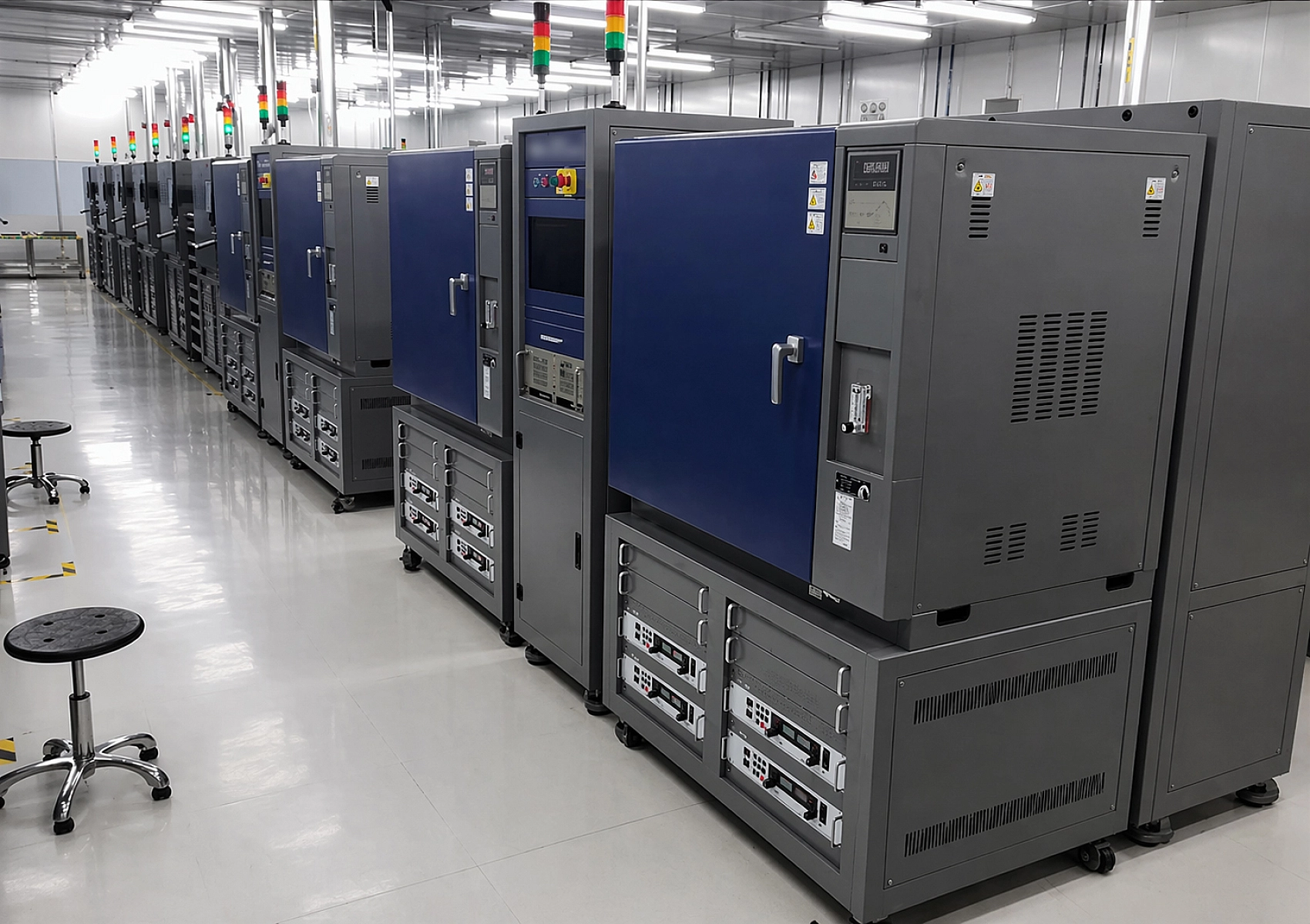
Parametric DPT characterization typically sweeps across multiple bus voltages per device, for example 400 V, 600 V, 800 V, 1000 V for a 1200 V SiC MOSFET, with DPT shots repeated at each setpoint. The supply has to move between setpoints cleanly and quickly. MagnaLINK distributed DSP digital control on the SLx Series implements programmable slew rates and fast programmable ramping with field-tunable gains across a wide range of load conditions, letting an automated sweep sequencer step through a full voltage-current-temperature matrix.
Digital commands over a network interface has inherent latency typically milliseconds, which can introduce jitter into tightly-coordinated DPT sequences. For applications where the supply's state needs to synchronize with the gate driver, AFG, and oscilloscope without going through the command layer, the SLx and Series provides a standard D-Sub User I/O with analog and digital logic. This I/O provides a hardware path for real-time feedback and control that's independent of the software command interface, allowing the supply can be wired directly into the test bench's interlock system, trigger logic, and analog measurement paths.
Automation infrastructure varies widely across the DPT customer base, including LabVIEW, Python over Ethernet, IVI drivers in TestStand, production floors running PLC controlled sequencers. The supply needs to integrate with whichever infrastructure is already in place, not force a change in it.
The SLx Series comes standard with dual USB (front and rear) and RS-485, with full SCPI and Modbus command-set support. Optional LXI TCP/IP Ethernet (+LXI) provides standard lab network control, and for environments running industrial automation, SLx additionally offers CANopen, EtherCAT, EtherNet/IP, ModbusTCP, and PROFINET as fully-integrated communication options, each with full command-set support, enabling direct control from industrial PLCs (Siemens PROFINET being particularly common in semiconductor fabs and automotive test cells). The XR Series comes standard with serial RS-232 and supports LXI TCP/IP Ethernet (+LXI) and IEEE-488 GPIB (+GPIB) as optional interfaces for broader lab instrumentation integration. National Instruments LabVIEW and IVI drivers are included with every supply.
Starting from Python–what Magna-Power uses in-house for its own test software–is straightforward the supply listens on a socket, SCPI commands are ASCII text, and a full DPT sweep scaffolding with logging takes a dozen lines:
import socket, time

# Connect to supply at lab network address, default SCPI socket port
s = socket.socket(socket.AF_INET, socket.SOCK_STREAM)
s.connect(('192.168.0.86', 50505))

# Identify and configure for remote control
s.sendall(b'*IDN?\n')
print(s.recv(4096).decode())
s.sendall(b'CONF:SOUR 0\n')

# Sweep across bus voltages for parametric DPT characterization
for v_bus in [400, 600, 800, 1000]:
    s.sendall(f'VOLT {v_bus}\n'.encode())
    s.sendall(b'OUTP:START\n')
    time.sleep(0.1)   # settle time before DPT shot
    # [trigger AFG, capture scope waveforms, calculate E_on/E_off]
    s.sendall(b'MEAS:ALL?\n')
    curr, volt, pwr = s.recv(4096).decode().split(',')
    print(f'V_bus={v_bus}: measured {float(volt):.2f} V, {float(curr):.3f} A')

s.sendall(b'OUTP:STOP\n')
s.close()
Self-protecting topology under load faults
DPT is inherently destructive testing. Devices routinely fail, and when they do, they typically short. The supply must respond to a load fault without cascading into supply damage, without injecting large reverse currents back into the capacitor bank, and without releasing stored energy in ways that propagate damage through the bench.
Every MagnaDC power supply supply is built on Magna-Power's signature current-fed power processing topology, which adds a control stage over conventional voltage-fed designs. Under fault conditions, this topology inherently limits fault energy: no fast-rising current spikes, no magnetic core saturation, and self-protecting behavior under short-circuit loads. For DPT applications, this is the first line of defense when a DUT fails: the power supply architecture itself resists the fault, rather than relying on firmware-controlled trip responses. Combined with the safety protections in the following section, the SLx Series and XR Series tolerate repeated DUT-failure events without taking the bench down.
Safety protections
DPT pushes devices to failure by design. A well-designed supply provides multiple layers of protection that together shield the supply, the bench, and the operator from the range of things that can go wrong, DUT shorts, runaway currents, overvoltage transients from the cap bank, thermal excursions, enclosure breaches, and operator errors. The protection strategy is layered rather than single-point: each mechanism operates independently, so no single failure defeats the whole system.
Programmable overvoltage trip (OVT) and overcurrent trip (OCT) are the first programmable layer. Both SLx Series and XR Series supplies provide OVT and OCT settings configurable from the front panel, User I/O, or via command interface, with trip thresholds independent of the output regulation setpoint. For DPT, OCT is typically set a modest margin above the expected recharge current so that any anomalous load behavior.
For thermal protection, distributed thermal switches monitor multiple points inside the supply, and control-integrity diagnostics watch the programming line, remote sense leads, and internal references. A fault on any of these conditions trips the supply independently of the programmable OVT/OCT settings.
A dedicated Interlock hardware input that inhibits the output when a contact loop is broken with a latching fault. The Interlock typically integrated with the test enclosure: a 5V-referenced dry-contact loop runs through the enclosure door, the fixture cover, and any other safety-critical interlocks. Opening any link disables the output. Both the SLx Series and the XR Series provide an interlock input as a standard feature; this is the baseline hardware safety layer that every DPT bench should tie into its enclosure and access controls.
A dedicated hardware emergency stop is available on the SLx Series as an additional layer. The E-stop input, when triggered by a 24V signal, creates an AC-interrupt path that bypasses all logic, processors, and control firmware. This provides a hardware-only shutdown mechanism independent of the supply's control electronics, which is useful in installations where an additional layer of hardware isolation beyond the interlock is desired.
Combined, these mechanisms let the supply tolerate repeated DUT failures — the kind of destructive testing that characterization work actually requires, without propagating damage through the bench.
Rack Density
DPT setups are instrument-heavy: oscilloscope, function generator, gate driver supply, thermal chamber controller, automation hardware, and the DC bus supply.
Magna-Power's SLx Series delivers up to 10 kW at voltages to 3,000 Vdc in a single 1U chassis, where a conventional high-voltage programmable supply typically occupies 3U or more. Part of the reason is architectural: many competitive supplies include auto-ranging output stages to offer constant power across a wide envelope, which adds parts count, cost, control complexity, and physical volume. For DPT, the test voltage is set by the DUT and the average current demand is known from the sizing analysis; auto-ranging. Fixed-range supplies sized for the target device class deliver the same useful capability in less space at lower cost.
Where DPT Is Going
Several trends in wide bandgap device development are directly relevant to the DC supply side of the DPT bench:
- Higher voltages. 3.3 kV SiC is in volume production. 6.5 kV and 10 kV SiC devices are moving from prototype to early commercial availability. DPT bus voltage requirements are climbing with them.
- Higher currents and module-level testing. Characterization at hundreds of amperes to kiloamperes is increasingly common, which raises energy-per-shot and capacitor bank recharge rate — exactly the parameters that make Section 5.2’s recharge constraint dominate over energy balance.
- Tighter integration with reliability testing. DPT is no longer standalone; it’s integrated with HTRB, HTGB, and power cycling on the same bench, which makes supply stability over long test durations a more demanding requirement.
- Automation at the production line. Parametric DPT on every production unit is becoming routine for some manufacturers, shifting the bottleneck from measurement to capacitor bank recharge time.
In every one of these directions, the DC bus supply requirements climb. The SLx Series at 3 kV and the XR Series at 10 kV are positioned to follow the devices upward, in the 1U and 2U form factors that keep the rest of the DPT bench buildable.
References
Wang, F., Zhang, Z., and Jones, E. A. (2018). Characterization of Wide Bandgap Power Semiconductor Devices. IET Energy Engineering Series, Vol. 128. Stevenage, UK: Institution of Engineering and Technology. ISBN: 978-1-78561-491-0.
IEC 60747-9:2019, Semiconductor devices – Discrete devices – Part 9: Insulated-gate bipolar transistors (IGBTs), Edition 3.0. Geneva: International Electrotechnical Commission, November 2019.
JEDEC Solid State Technology Association (2021). JEP182: Test Method for Continuous-Switching Evaluation of Gallium Nitride Power Conversion Devices, Version 1.0. Arlington, VA: JEDEC.