


Thermal Paste Surface Application in Power Electronics Manufacturing
An overview of different thermal paste surface application methods, specific to power electronics manufacturers, who have extreme power dissipation requirements that demand consistent thermal performance.
Overview
Reliable and compact power electronics designs must consider thermal transfer. The power losses from semiconductor switching and conduction must be extracted and transferred to heatsinks, which are often constructed of copper or aluminum for their high thermal conductivities. Poorly prepared semiconductor and heatsink mating surfaces can limit the effectiveness of this heat transfer. Machining surfaces smooth and filling air gaps between surfaces are two simple techniques that consistently lower thermal resistance in production environments.

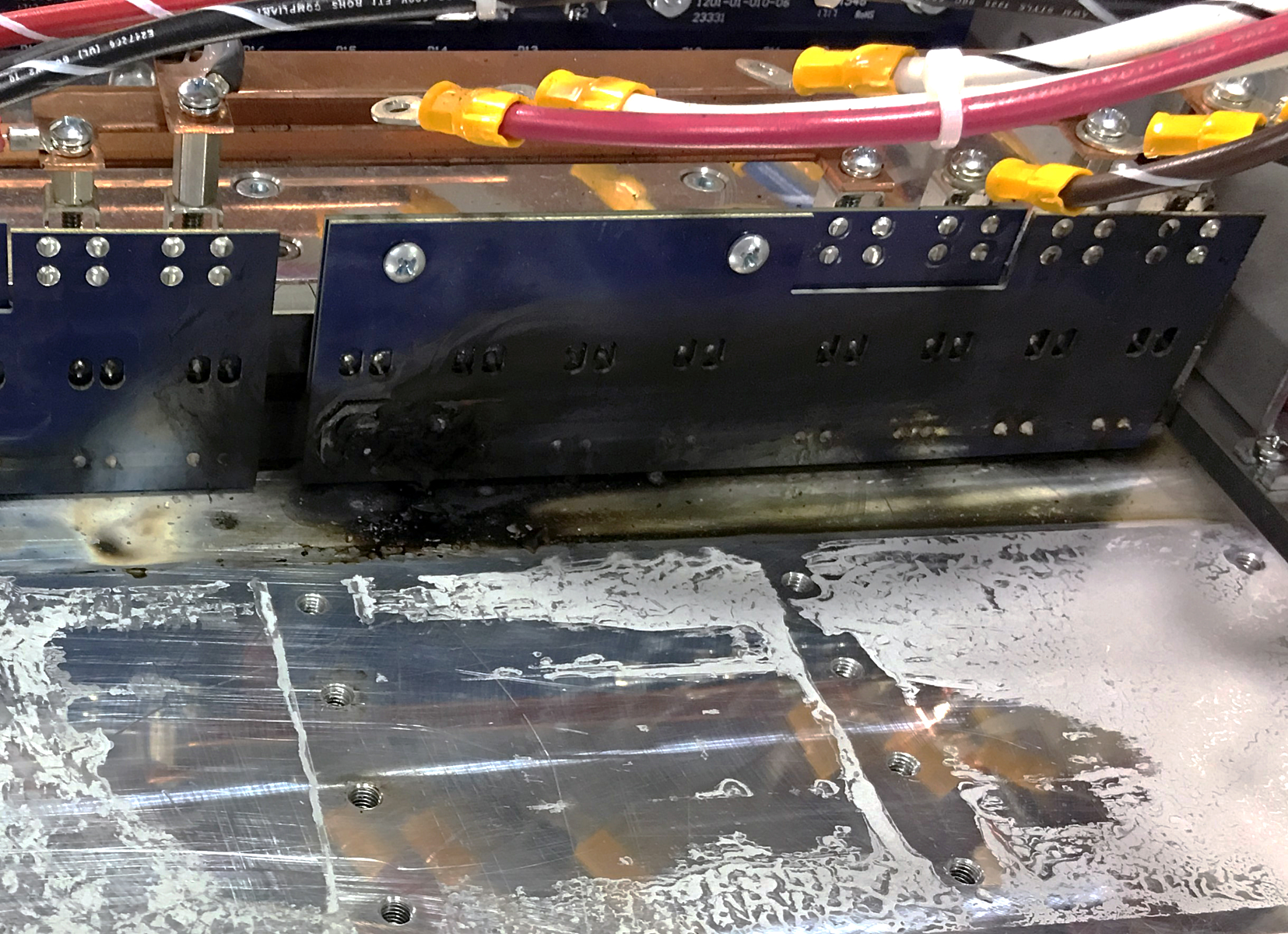
Without gap filling, air will fill the voids, which will restrict thermal energy transfer as a poor thermal conductor (0.026 W/mK). Metal-to-metal interface and poorly controlled gap filling can lead to unpredictably high thermal resistances, which can overheat and damage components. When coupled with poorly placed thermal sensors or lack of thermal protection, poor heat dissipation can even lead to fires.
Thermal interface material (TIM) displaces air with thermally conductive material. Available in many substances with improved ranges of thermal conductivities from 0.6 to 6 W/mK, TIM is recommended for long-term, repeatable, and efficient heat dissipation.

In 2014, Magna-Power began formulating its own thermal compound and surface application procedures for use in high power density 10 kW power supplies. Both became especially crucial when Magna-Power started developing electronic loads, a demanding application with 100% power dissipation. Magna-Power’s thermal paste, Pitel Paste, balances application ease, cost, and thermal resistivity. Pitel Paste can also be produced in large batches for Magna-Power’s broad range of programmable DC power products. Regularly used in 2000 V power assemblies, Pitel Paste is successfully implemented with tightly controlled paste production and drip-free surface application.
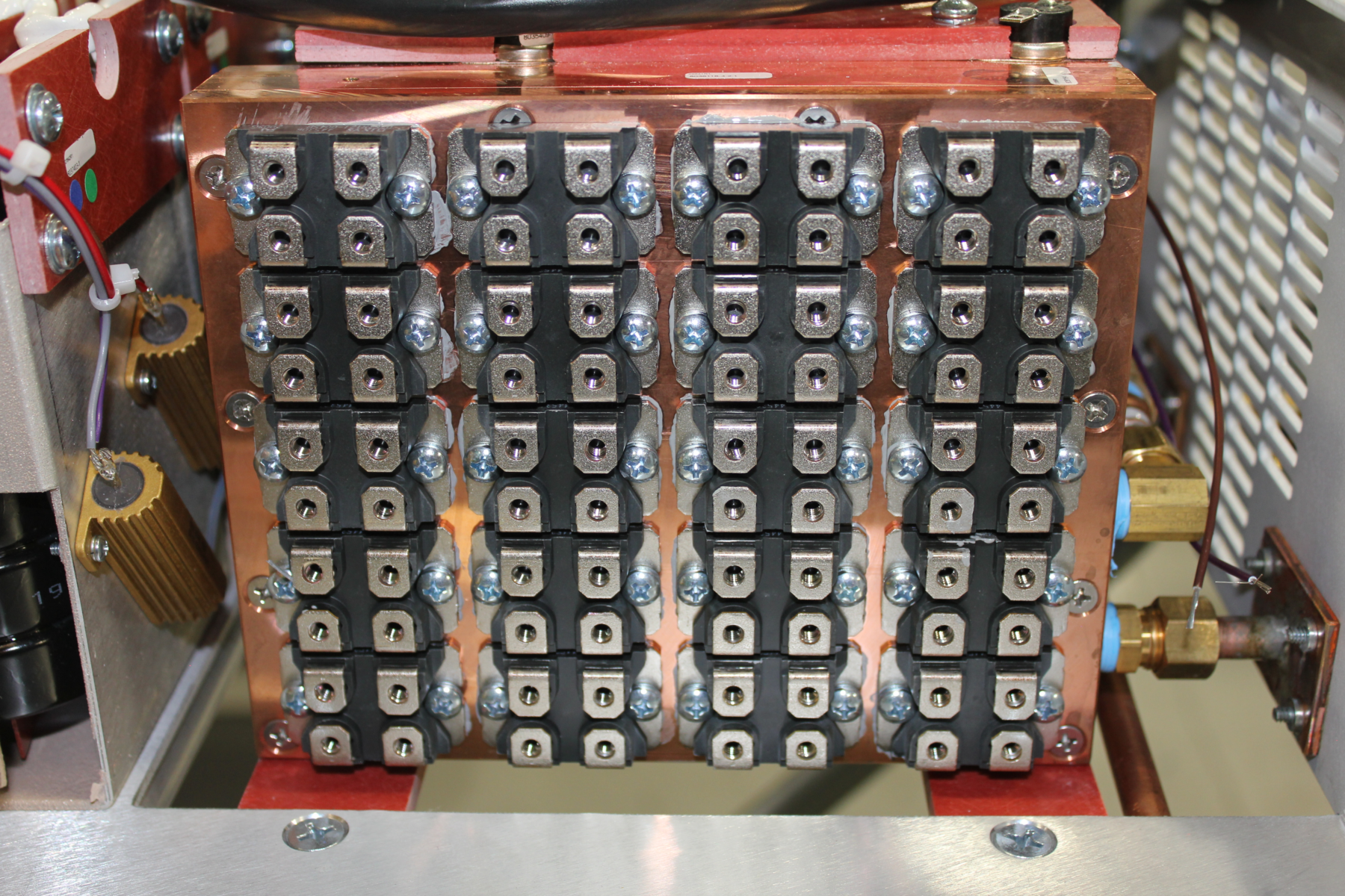
As a manufacturer with over 375,000 available product configurations, Magna-Power produces a broad range of power electronics assemblies, which need thermal paste for power semiconductor cooling.
Thermal paste surface application is critical for filling air gaps. When establishing methods, there are several physical factors to consider, including: paste viscosity, heat dissipation requirements, surface roughness, semiconductor package type, etc. Manufacturing practicality should also be taken into account, for example selecting automated techniques for mass production, or manual methods to accommodate quick changeover.
The paper focuses on thermal paste surface application methods specific to power electronics, which have extreme power dissipation requirements that demand consistent thermal performance. These methods reflect Magna-Power’s leadership and experience in power electronics design and production. Thermal paste application methods may vary from those described in this paper, depending on engineers’ design and production requirements.
Application Methods
Thermal paste application varies based on at which stage in production the paste is applied, the type and size of the heatsink, and the semiconductor package (TO-220, TO-247, SOT-227B, DO-5, etc.).
The recommended thermal paste application volume is determined by interface dimensions and assembly methods. When filled with thermal paste, the distance between the heat source and heatsink is called the bond-line thickness, which is ideally less than 25 µm. However, based upon manufacturing and application requirements, the bond-line thickness can be as much as 100 µm.
The target bond-line thickness can be achieved using different thermal paste application methods, including spatula (also known as trowel or comb) spreading, pneumatic dispensing, positive displacement dispensing, stenciling, and roller deposition. Several thermal paste application methods are discussed and relatively scored based on:
- Automation: the level of dependence on manual process versus machinery, correlating with the amount of labor involved and repeatability
- Volume Precision: the level of control over the amount of paste applied
- Placement Precision: the precision with which paste is located on the surface
- Setup Cost: how expensive the required equipment is
Dispensing
Dispense Patterns
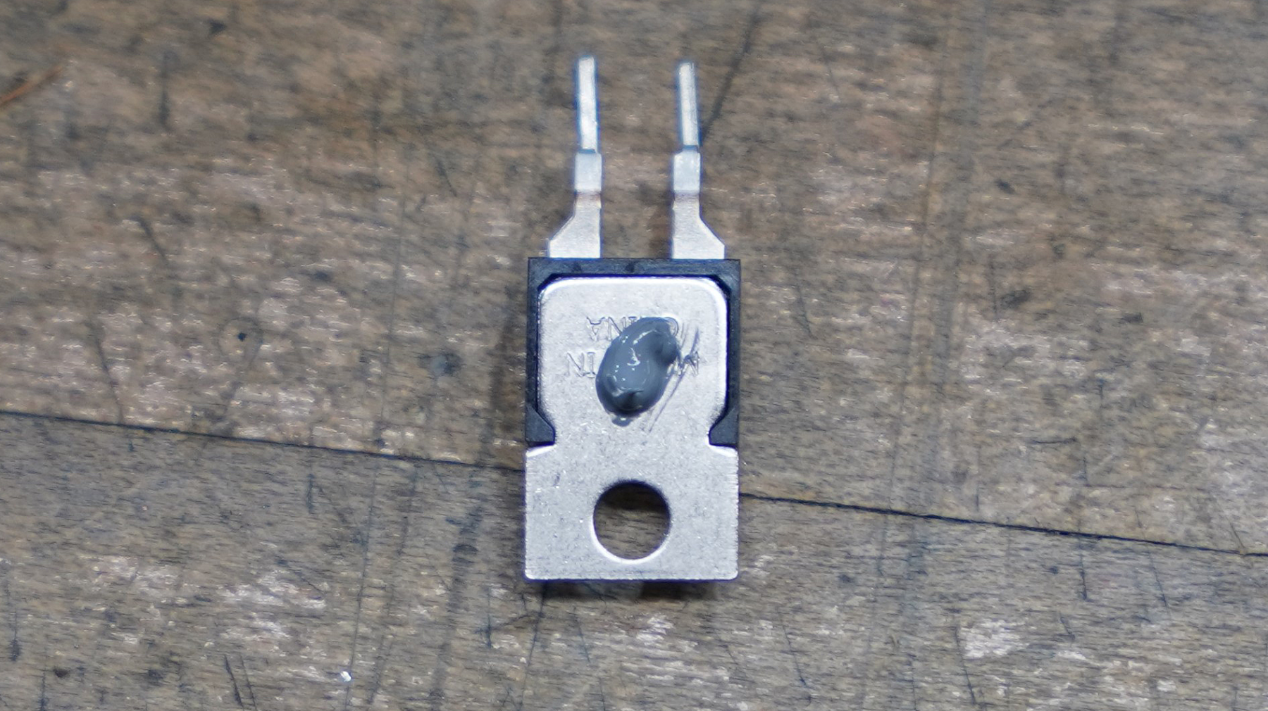
Direct dispensing is the act of depositing thermal paste on a thermal interface without spreading. It is typically manual in low-volume high-mix manufacturing and automated in high-volume low-mix manufacturing. Manual dispensing has poor placement precision and accuracy.
A common dispense pattern is colloquially known as the “Hershey Kiss” for its appearance. A single dot for small devices that have a maximum footprint of 20 x 20 mm is simpler, faster to apply, and accomplishes almost the same coverage after pressure is applied when compared to more intricate patterns. When a device with the applied single dot pattern is compressed, the paste spreads uniformly, filling air gaps between the device and heatsink. This pattern works well with square surface areas. If the area is rectangular, then a single line of thermal paste is recommended for improved coverage.


Dispense Volume
It is critical that the bond-line thickness is consistent along the full surface area of the device. The following factors are required to achieve consistent bond-line thickness: measured volume dispensing, specific pattern application, and measured torque for device clamping. Uniform clamping pressure is needed along the entire metal case of the semiconductor to evenly spread the paste.
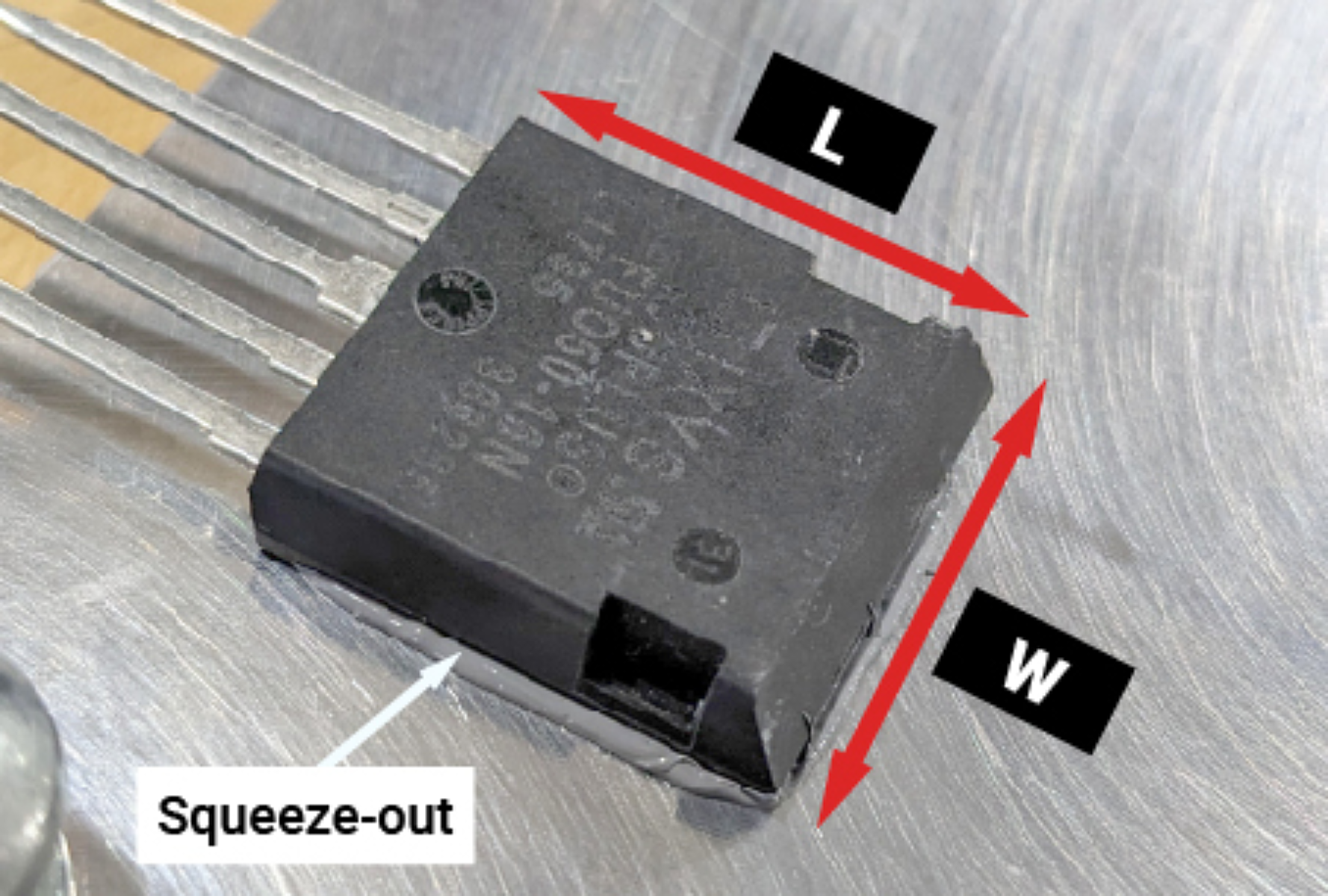
The specific thermal paste application volume can be estimated using a simple calculation. This calculation must consider the device footprint and target bond line thickness, factoring in thermal paste squeeze-out along all four sides of the device after it is installed. The squeeze-out provides a mechanism to visually inspect paste coverage. A mounted device passes inspection when thermal paste is visible (but not excessive) along all four sides, as shown in Figure 8. The same visual inspection method can be applied to stencil designs (discussed later in this paper) by enlarging stencil apertures and/or thickness. Stencil printing processes inherently produce consistent volume and placement. Visual inspection of the stenciled surface prior to assembly is sufficient.
The baseline thermal paste volume can be established using a simple calculation of the power device’s surface area, multiplied by maximum bond-line thickness, e.g. 25 µm (Equation 1). Typical squeeze-out is 1-2 mm around the package perimeter, which can increase the required TIM nearly tenfold, as shown in Table 1. To estimate the squeeze-out volume, a simplified cylindrical model is applied (Equation 2). The total device perimeter is multiplied by a circular cross-section area of 1 mm in diameter. This should be added to the total required volume in µL.
Where `L` is the device length, `W` is the device width, `t` is the bond-line thickness and `d` is the diameter of squeeze-out.
| Device Package | TO-220 | TO-247 | i4-Pac | SOT-227B | RH-50 | 7-MTPB | TO-244 |
| Case (LxW) [mm] | 10.16×15.1 | 15.97×20.81 | 19.87×20.65 | 24.98×38.11 | 16.2×49.8 | 31.76×63.41 | 19.03×92.44 |
| Interface volume @ raw bond-line thickness [µL] | 3.8 | 8.3 | 10.3 | 23.8 | 20.2 | 50.3 | 44 |
| Squeeze-out volume at 1 mm OD [µL] | 39.7 | 57.7 | 63.6 | 99.1 | 103.6 | 149.4 | 175 |
| Total Thermal Paste Volume [µL] | 43.5 | 66.1 | 73.9 | 122.9 | 123.8 | 199.8 | 219 |
Dispensing Equipment
The most basic form of dispensing is a manual barrel and piston tool, i.e. syringe and caulk applicator. More advanced dispensers are power operated, automated and have volumetric control. Dispensing requires paste that is shear thinning for ease of spreading. The paste must also have a low thixotropic index for dispensing accuracy, particularly when dosing small volumes. A high thixotropic index can present challenges to dispensing paste with precision and repeatability.
Pneumatic systems have limited programming with pressure and dwell time as inputs. The inputs only correlate with actual dispense volume coming out of the syringe, and therefore have poor precision and reproducibility. Pneumatic systems are prone to losing volumetric dispensing accuracy as the cartridge starts to empty. The net effect of this phenomena is that the dispense quantity is likely to decrease as the cartridge is depleted.
Manually dispensed volume from caulk applicators is not finely controlled, but the setup cost is low. This type of dispenser is best suited in combination with stencil deposition.
| Category | Automation | Volume Precision | Placement Precision | Setup Cost |
| Score | N/A | Fair | Fair | Very Low |
| Category | Automation | Volume Precision | Placement Precision | Setup Cost |
| Score | Great | Fair | Fair | Low |
Positive displacement systems can be programmed to ensure repeatable volume precision, which is an improvement over pneumatic systems. The correct amount of applied thermal paste is guaranteed for long production runs with these systems.
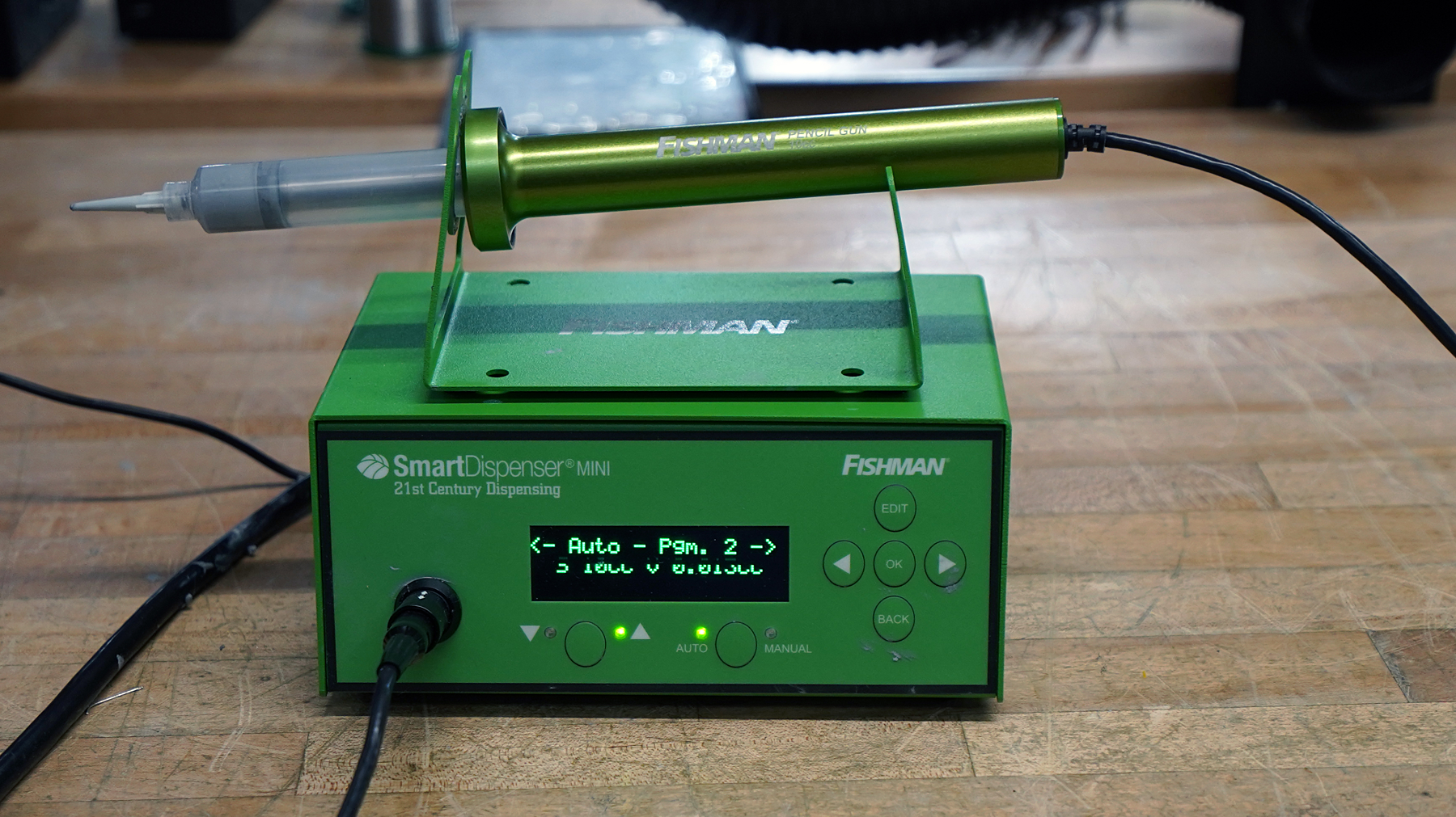
| Category | Automation | Volume Precision | Placement Precision | Setup Cost |
| Score | Great | Great | Fair | Low |
Spatula Spreading
Spatulas are frequently used in low-volume manufacturing. With this method, thermal paste is first deposited onto the device or heatsink. Then, a hand-held spatula is used to evenly spread thermal paste across the surface. A few strokes are often required to deposit evenly distributed lines of TIM. This method is a manual operation, prone to human error, and requires larger TIM amounts to ensure complete coverage, leading to larger squeeze-out. Despite its shortcomings, spatula dispensing is common in commercial production due to its low setup cost and basic equipment requirements.

| Category | Automation | Volume Precision | Placement Precision | Setup Cost |
| Score | Poor | Fair | Fair | Very Low |
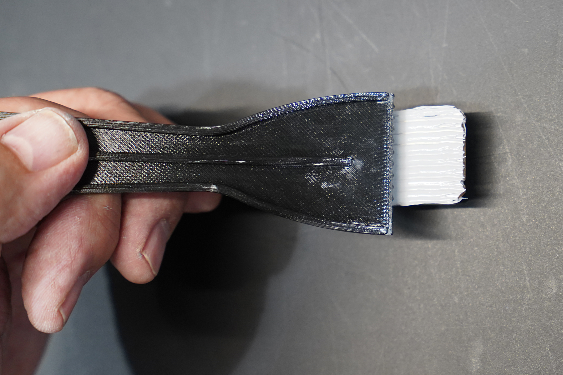
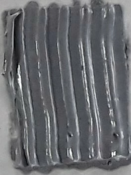
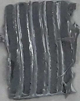
Manual Spreading Serrated-Edge Spatula
Given the same set up and altering the angle of attack of the spatula, the deposition’s fidelity and mass are both affected.
Manual spreading introduces variabilities in spatula angle, stroke length, stroke path, and pressure that lowers repeatability as changes from operator to operator. Fig. 11 shows different paste masses for the same area and different spatula angles (specified in degrees with respect to the applied surface). The serrated-edge spatula shown in Fig. 10 is used in Magna-Power production and is publicly available for download from pitelpaste.com as 3D printable files.
Stencil Deposition
Chemically etched stencils (and later, laser cut) have been used in electronics manufacturing since the early 1980s. Stencils were primarily implemented for quickly and reliably depositing solder paste on printed circuit boards. The technology can also be used for thermal paste, by pre-applying the paste to heatsinks and power modules.
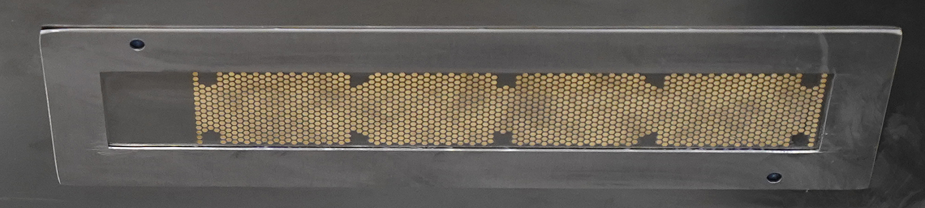
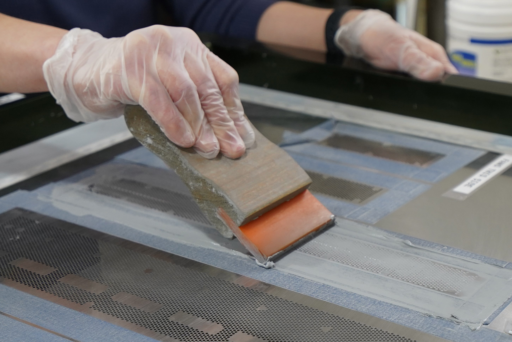
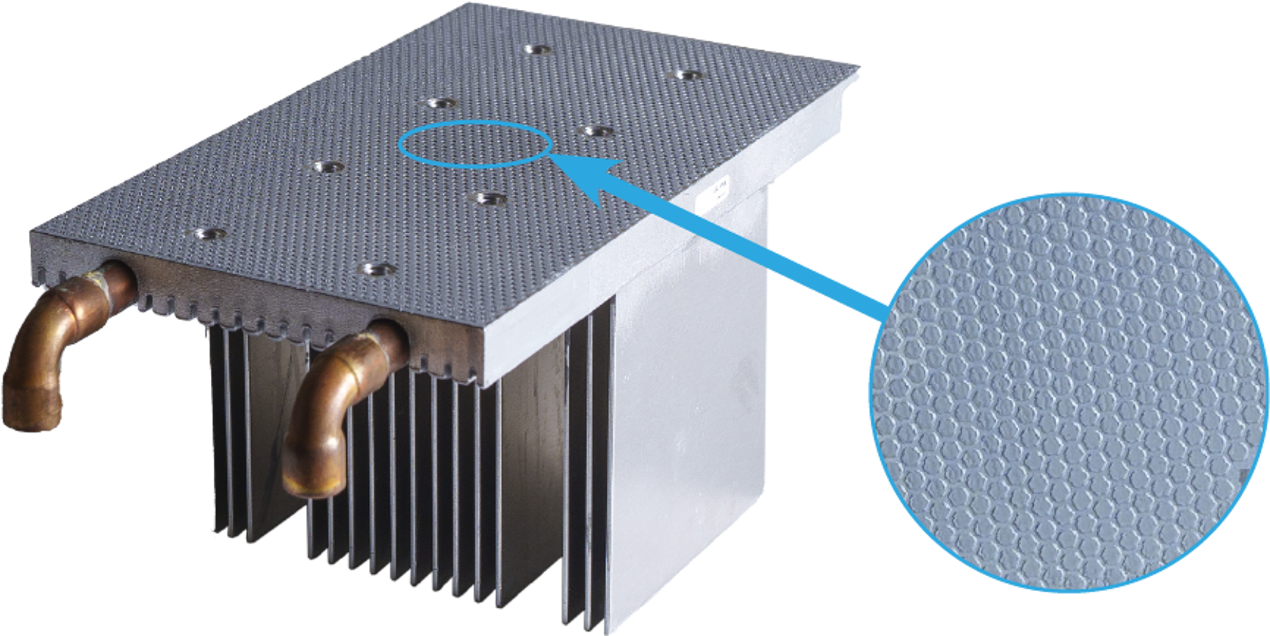
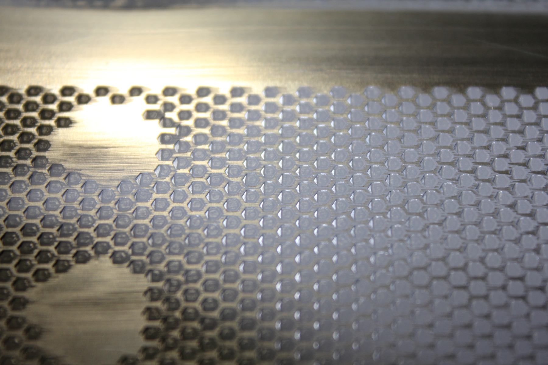
Stencils are cut from a stainless steel foil that typically ranges in thickness from 0.075 mm to 0.15 mm. For surface mount technology, solder paste stencils are both widely understood and easily obtainable through various stencil manufacturers. Adapting this same technology to TIM stencil printing is an easy transition that allows limitless deposition geometries. At Magna-Power, a repeating hexagon aperture was selected for controlling paste coverage and volume.
With high-power electronics assemblies, heatsinks can be long, tall, and oddly shaped, where traditional stencil printers (targeting solder paste) are not suitable.. Magna-Power’s numerous heatsink designs cover wide ranges in x-y positions and z-height. To accomplish the x-y positioning, a custom surround plate (Fig. 12) was attached underneath the stencil. The surround protects the 0.127 mm thick stencil foil from “coining”, which is damage caused by excessive squeegee force. Heatsink height variation is managed by adjusting frame height with set screws or by adding spacers to the printer base.
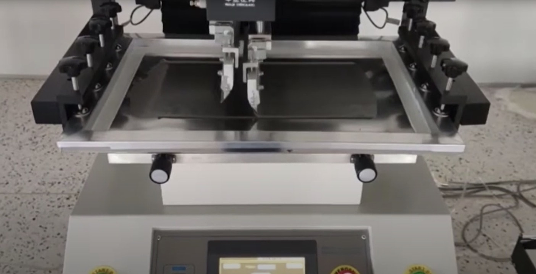
Commercial paste printing systems range from basic manual systems, consisting of frame-mounted stencil with a clamshell lifting mechanism, to semi-automatic systems, consisting of built-in squeegee with programmable strokespeed, pressure, and stencil separation speed.
Aperture Filling And Paste Deposition Process
For thermal paste printing via a foil stencil, there are four factors that ensure consistent aperture fill and deposition pattern fidelity (as shown in Figure 14):
- Squeegee angle of attack (AoA)
- Squeegee stroke speed
- Squeegee downward pressure
- Stencil separation

Combining squeegee angle of attack, pressure, and stroke-speed allows the thermal paste to roll ahead of the blade, providing repeatable and complete aperture fill.
When a stencil is lifted from the print surface, paste can stick to the sides of the aperture, which can deform the deposition pattern, as shown in Fig. 16. Controlled stencil separation can mitigate the issue by enforcing a slow and constant lift velocity. The slow speed allows paste more time to separate from the stencil side walls and reduces foil warping, which improves pattern fidelity and makes the volume consistent. Programmable speed makes the print process repeatable and tunable.
| Category | Automation | Volume Precision | Placement Precision | Setup Cost |
| Score | Good | Good | Great | Low |
Roller Deposition and Spreading
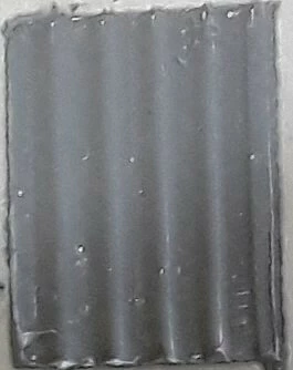
Rollers are a fast-to-apply, inexpensive, simple, and easy to use surface application solution. The paste is fed into the roller by a squeeze bottle attached to the handle. Rollers are able to quickly cover large areas like heat sinks and large power modules. Foam rollers are soft, absorb paste readily, and conform to irregular surfaces. The roller is not a precise method. The paste volume is loosely correlated to the foam density (pores per inch) and absorption depends on paste viscosity. A wet film thickness gauge can be used to validate layer thickness when experimenting with paste/roller combinations.
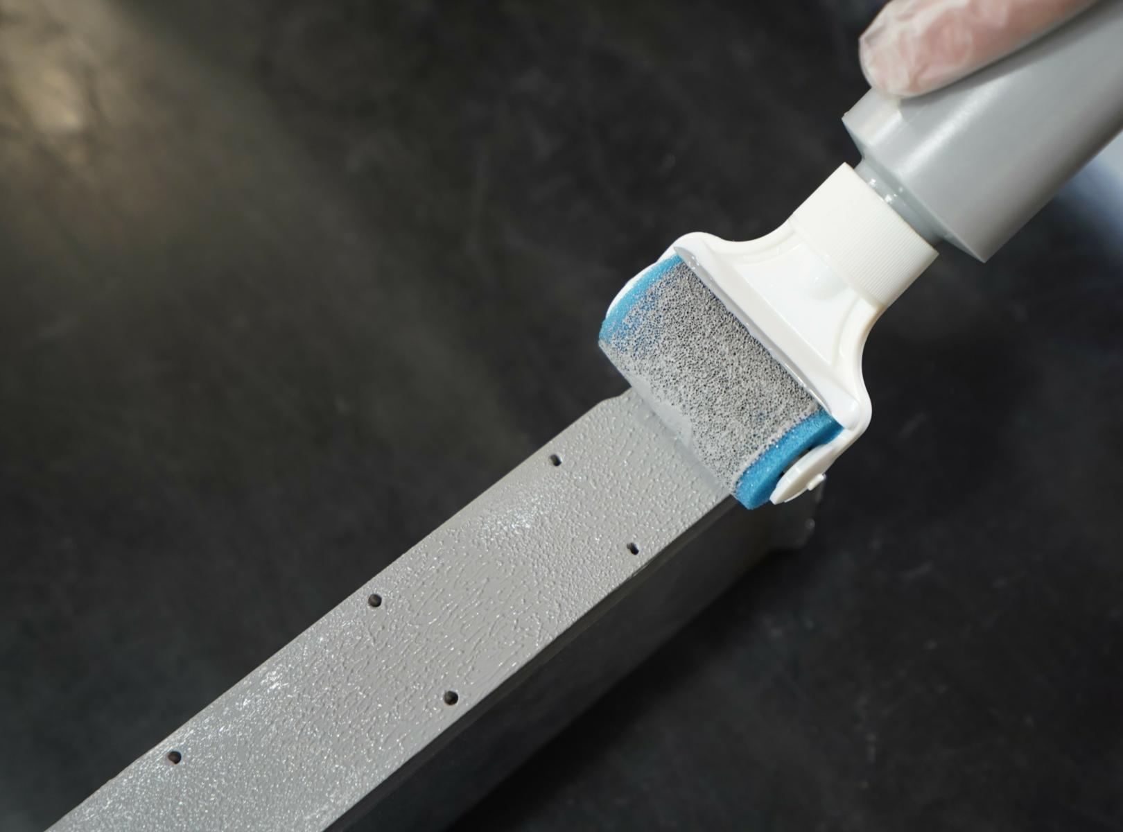
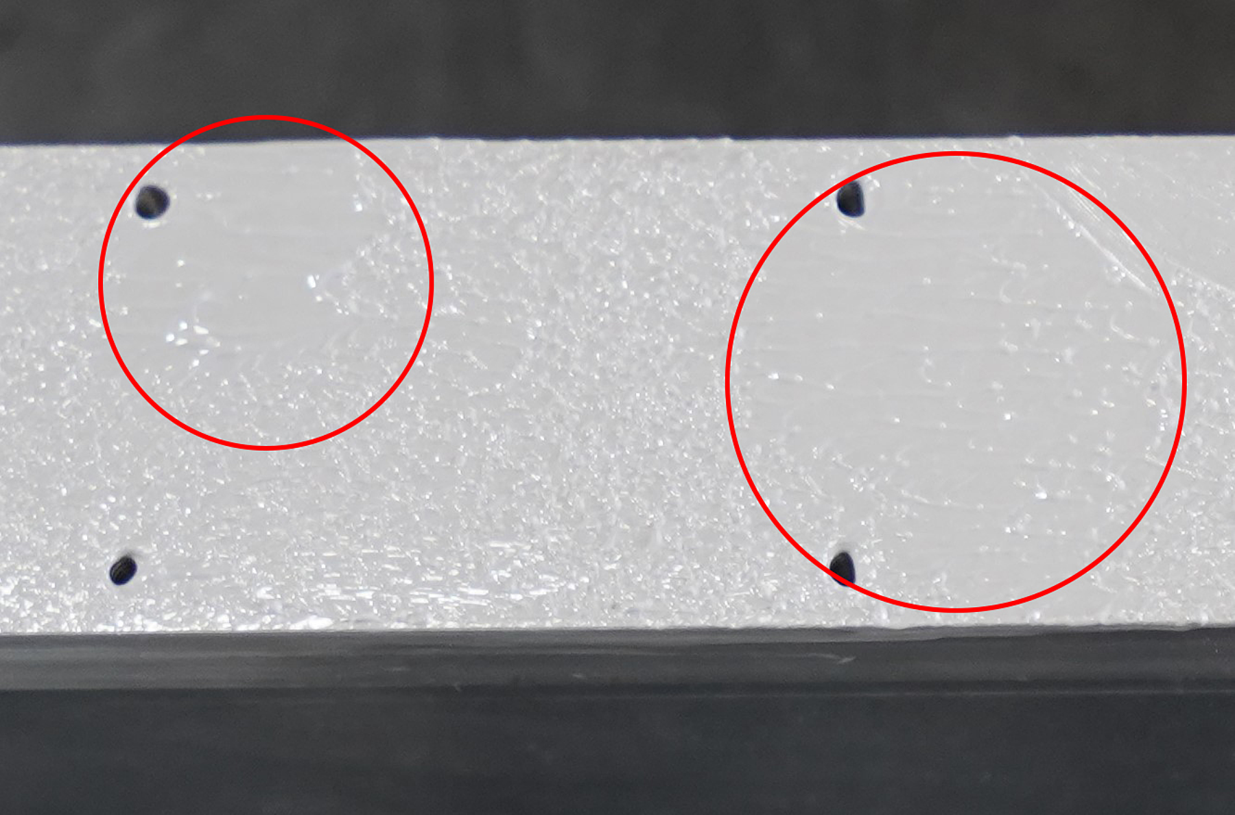
Despite their low cost and ease-of-use benefits, rollers deposit paste unevenly and with poor volume precision, as shown in Fig. 17. Roller spreading is best applied using low-viscosity thermal paste. Low viscosity pastes typically have less filler, which lowers thermal conductance (worsens performance).
| Category | Automation | Volume Precision | Placement Precision | Setup Cost |
| Score | Poor | Poor | Poor | Very Low |
Conclusion
Each thermal paste application method has advantages and disadvantages. For example, while setup cost for the roller method is relatively low, it is not automated and has poor volume and placement precision. To select the method that is best suited for a given application, several factors need to be considered, including: thermal paste characteristics, volume and placement precision requirements, and setup cost. When starting to integrate thermal paste into production, simple methods like spatula spreading, manual dispensing, and roller methods provide a low cost of entry. Production processes involving heat sinks with large surface areas will benefit from implementing stencils, which offer a compromise among automation, setup cost, and precision of volume and placement. For high volume, highly automated production, positive displacement or pneumatic dispensing provide additional benefits.
For nearly a decade, Magna-Power has iterated and successfully applied Pitel Paste for very demanding power electronics applications. The thermal paste application techniques researched and implemented by Magna-Power can be used by design and production engineers as a reference to produce consistent and high-performance thermal transfer in their assemblies.
| Application Method | Automation | Volume Precision | Placement Precision | Setup Cost |
| Manual Dispensing | N/A | Fair | Fair | Very Low |
| Pneumatic Dispensing | Great | Fair | Fair | Low |
| Positive Displacement Dispensing | Great | Great | Fair | Low |
| Spatula | Poor | Fair | Fair | Very Low |
| Stencil | Good | Good | Great | Low |
| Roller | Poor | Poor | Poor | Very Low |